A simply supported beam is prevented from moving transversely at its two supports while its ends remain free to rotate. In the small-deflection Euler-Bernoulli beam equation, a uniform span with transverse displacement and positive beam flexural rigidity has the support boundary conditionsHere is Young's modulus and is the second moment of area about the bending axis. The second pair expresses zero applied endpoint bending moment, since in the convention used here. It does not set the endpoint beam cross-section rotation or slope to 0. A clamped boundary condition instead constrains both displacement and slope.
For an original derivation, apply a downward central point force and take positive downward. Assume small elastic deflections, constant and no axial preload. Symmetry and force balance give an upward reaction at each support. On the left half, the bending moment is , so . Integrate twice, using and the symmetry condition , to obtainThus the midspan compliance of a simply supported beam isThe endpoint slopes are and : they are generally nonzero. This support geometry and central-load formula are used to infer material stiffness from a three-point bending test.[ref]
The moment-free natural boundary condition for a beam also follows from the principle of virtual work. For a central load, the total potential energy is . An admissible virtual displacement satisfies , while its endpoint first derivatives remain free. Two integrations by parts produce the boundary contributionThe terms multiplying vanish because the endpoint displacements are prescribed. Arbitrary endpoint values of then require there. The free end rotation and zero end moment are conjugate parts of the same variational boundary condition.
Clamping both ends changes the central-load deflection to , one quarter of the simply supported value for the same . It introduces endpoint reaction moments; it does not merely rename the same support. The clamped-beam Green function provides the corresponding fourth-order boundary-value solution. The support conditions likewise determine the simply supported beam normal modes, so a static stiffness measurement and a vibration measurement must use the same mechanical support model when they are compared.
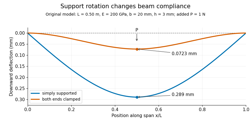
Original central-load beam profiles: allowing support rotation gives four times the midspan deflection of clamping both ends.
Details. 
A three-point bending test places a specimen on two separated supports and applies a central force. A load cell measures force, and a midspan displacement readout measures response. A direct plunger and extensometer can measure specimen deflection separately from machine crosshead displacement, as in the published Instron fixture arrangement.[ref]
Three Point Bend Test Fixtures by Instron. Principle of Operation and midspan deflectometer description
Fitting a proportional small-load segment estimates , where is the measured incremental midspan compliance. Record support spacing, load position and cross-section dimensions with that estimate.For stipulated , rectangular width , thickness and , the second moment of area is and . An incremental central load gives incremental deflection under the simply supported model, versus for the clamped model. Incremental readings remove an unchanged baseline deflection in this linear model; support settling, contact indentation and large rotations require separate interpretation.
A three-point flexural test loads a specimen through one central contact while two separated supports carry the reactions. In a small-deflection simply supported beam model, an incremental central force and the resulting midspan displacement determine the midspan compliance of a simply supported beam. With a known second moment of area, that response yields a flexural modulus.[ref]
Beam Displacements by David Roylance. Introduction; Example1 and equation7
The apparatus must distinguish specimen deflection from machine travel. The manufacturer's fixture description uses adjustable lower anvils and a central loading member; a direct midspan plunger can transmit deflection to an extensometer. A load cell supplies the force record.[ref] The crosshead displacement can also contain deformation of the frame and contacts.
For an original readout example, stipulate span , width and thickness , so . Suppose a linear loading interval gives direct midspan compliance , while machine travel gives . Applying the same beam relation to the two readouts givesThe apparent modulus is twenty percent lower. The numbers are chosen to isolate the displacement-channel effect; they do not characterize a particular fixture. Inferring a material Young's modulus further assumes the beam's linear, homogeneous bending model is adequate. Contact indentation, support motion and transverse shear strain can otherwise alter the measured compliance. The parent simply supported beam supplies the deflection derivation and support-comparison figure.
The moment-free natural boundary condition for a beam is the zero-end-moment condition obtained when an endpoint can rotate freely and no external couple is applied there. For positive beam flexural rigidity , it is . This differs from prescribing the endpoint beam cross-section rotation.
The simply supported beam gives the full principle of virtual work derivation. At its right support, the admissible virtual displacement obeys , but is arbitrary. The remaining bending boundary contribution is . Its vanishing for every permitted end rotation requires . Beam virtual work pairs end moments with rotation variations and forces with displacement variations.[ref]
An original modified boundary example shows why the missing external couple matters. Define a signed right-end couple by its external virtual work . The boundary coefficient then becomes , so the free-rotation condition is . With and , the endpoint second derivative is , not zero. This sign definition fixes the couple convention explicitly.
Clamping instead sets ; that restriction permits an unknown reaction moment rather than forcing it to vanish. Finite rotational restraint leads to a rotational spring boundary condition for a beam. These alternatives distinguish a prescribed motion from its conjugate natural load condition.
The midspan compliance of a simply supported beam is the incremental central deflection per incremental central load, with the support geometry fixed. For a uniform, small-deflection Euler-Bernoulli beam equation model without axial preload,Its units are length per force. The simply supported beam contains the derivation; the experimental use is to infer beam flexural rigidity or, with known geometry, Young's modulus.[ref]
Beam Displacements by David Roylance. Introduction and Example1, equation7
An original two-span example separates beam compliance from an assumed constant machine contribution. Suppose the same uniform specimen is tested over spans and . A machine-travel readout gives and . Assumewhere is unchanged between the tests. Subtracting the readings givesHence and . The inferred specimen compliances are and , with ratio . The raw readings have a different ratio because they include .
This beam compliance from two support spans relies on the unchanged-series-compliance assumption. Changing supports, contact indentation or shear contributions can invalidate it; two points fit its two coefficients without independently validating the model. A third span can test the cubic dependence. An incremental slope also differs from simply dividing a total displacement, including an initial offset, by the current force.
Beam compliance from two support spans separates a cubic span-dependent beam response from a span-independent contribution to the measured mechanical compliance. Assume the same uniform specimen, unchanged machine contribution and a small-deflection central-load model:Here is beam flexural rigidity and . The midspan compliance of a simply supported beam contains the basic numerical fit, while the beam source derives the cubic dependence.[ref]
Beam Displacements by David Roylance. Introduction; Example1, equation7
An original uncertainty example shows why distinct spans can still be too close. Let the actual model have , hence . Assign independent compliance standard uncertainties , and neglect span uncertainty for this example. Since the slope estimate is linear in the readings,Spans and give , about54percent of the actual coefficient. Using and instead gives about3.57percent with the same readout uncertainties. The close-span subtraction strongly amplifies those errors. At the larger relative uncertainty, simply treating as approximately linear is unreliable.
This conditioning of two-span beam compliance inference concerns measurement precision, separately from model adequacy. If shear adds a term proportional to , then has three unknown coefficients that two readings cannot identify. Changing contact or fixture compliance can likewise violate the assumed constant . Further spans and an independent deflection readout test those assumptions; two fitted points alone do not.
Conditioning of two-span beam compliance inference describes how perturbations in two measured compliances and support spans affect the inferred bending coefficient. In the model represents an unchanged series contribution and is beam flexural rigidity. The cubic beam term follows from the midspan compliance of a simply supported beam.[ref] The subtraction is sensitive when the spans are close, or when the beam-response difference is small compared with readout errors.
Let and temporarily treat the spans as exact. The sensitivity coefficients are and . Consequently,This is the standard measurement uncertainty propagation rule applied to a linear combination; the covariance term matters when the readings share errors.[ref]
For an original numerical comparison, stipulate , so , and independent standard uncertainties . Spans and give and , about 54 percent of . Increasing the second span to gives and , about 3.57 percent. The wider spacing makes the same compliance readout precision much more informative.
Span uncertainty enters through additional sensitivity coefficients:For uncorrelated span readings, their first-order contribution to is , before any compliance/span correlations are included. An identical additive readout offset cancels from , whereas a changing offset does not.
A practical span comparison holds the specimen, contacts, loading position and displacement channel as consistent as possible. Close spans amplify measurement noise; simply choosing distant spans can instead expose a failure of the assumed model. Shear produces a term proportional to , and changing contacts can change . A third span tests those assumptions. Finally, inversion to is strongly nonlinear near : the 54-percent case cannot be adequately summarized by a small symmetric relative uncertainty on .
A uniform elastic beam with endpoint conditions has normal modes for positive integers . Substitute into and impose the four endpoint conditions to obtain the displayed spectrum. Here is mass per unit length, is a second moment of area, and is beam flexural rigidity. frequencies proportional to distinguish flexural waves from the nondispersive ideal stretched string.
A prescribed initial beam profile may vanish at a pivot while having nonzero endpoint curvature. If the post-release pivot is moment-free, its bending moment condition is . The data then cannot have a classical solution with continuous curvature at the initial boundary corners. A finite-energy weak solution can still represent release from preparing end moments. For example has odd sine coefficients proportional to ; converges, giving finite bending energy. The displacement series takes the prescribed initial shape, but termwise endpoint second derivatives cannot be identified with its interior curvature limit. This conservative beam evolution does not have the immediate smoothing of a heat equation.
Articles by others on the same topic
There are currently no matching articles.