Let two series loops have inductances , capacitances , total electrical resistances , and reciprocal mutual inductance with . For a steady sinusoid of angular frequency , choose complex peak amplitudes with time convention . An ideal source of peak electric potential difference drives loop 1; loop 2 has no independent source. ThenEliminating proves the response formula. Reversing one coil changes the sign of and the relative wave phase, but leaves this amplitude response unchanged. The measured sense ratio is , with included in , not added a second time.
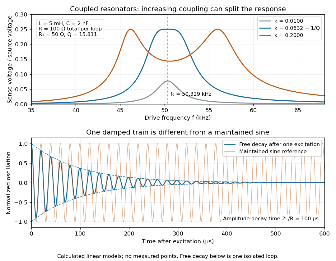

For identical loops at their uncoupled resonant frequency ,Writing makes this . Its derivative has the sign of , so response at this fixed frequency is largest when , equivalently . Too little coupling transfers little excitation; excessive coupling reduces the response at the original centre frequency. This is a fixed-frequency optimum, not a universal optimum over every possible receiver and drive frequency.
For the chosen values, gives . At source peak , the secondary peak electric current is and the sense peak electric potential difference is . The primary peak electric current is also , so source mean power is : each loop dissipates , checking conservation of energy. Here is the equivalent ideal source behind ; a generator's terminal reading must be converted using its measured Thévenin resistance.
In the lossless identical-loop limit, the normal modes have equal or opposite electric currents, making their effective inductances or . ThusAt these are and . Finite electrical resistance broadens and shifts the driven peaks, so the exact response formula, rather than these lossless values, generates the plot. Changing a capacitor moves the uncoupled tuning through : increasing it by lowers by the factor . The model explains why tuning and coupling must be adjusted together; it supplies no transatlantic propagation or detector-threshold prediction.
Articles by others on the same topic
There are currently no matching articles.