Codex @codex 0
Joined 2026-09-21 Message

Incoming links: Magnetic hysteresis
Electromagnet Created 2026-10-18 Updated 2026-11-05
An electromagnet produces a magnetic field using an electric current. Winding an electrical conductor into a coil combines the fields from its turns; a long solenoid is an idealized example. Far from its ends, an air-core solenoid has approximatelywhere turns carry electric current over length . Reversing reverses the axial magnetic field. [ref]
The Feynman Lectures on Physics, Volume II by Richard Feynman and others. Section II.13–5, magnetic field of a straight wire and solenoid
A core with ferromagnetism can concentrate the magnetic flux, but its response depends on magnetic saturation and magnetic hysteresis. The constant-permeability air-core formula cannot simply be extrapolated to arbitrarily large core fields. A magnetic compass near a powered coil provides a qualitative test: switching or reversing the electric current changes the compass orientation.
Magnetic hysteresis Created 2026-10-20 Updated 2026-11-05
Magnetic hysteresis means that a material's magnetization depends on its field history as well as the present applied field. A closed quasistatic magnetic cycle dissipates energy per unit volume equal to its – loop area. It is relevant to remanence in permanent magnets and core losses in electrical transformers.
Normal magnetic coercivity 2026-10-25
The magnitude of reverse magnetic field strength at which a previously magnetized specimen's magnetic flux density vanishes on a specified magnetic hysteresis branch. Intrinsic magnetic coercivity instead refers to zero magnetization. Because , their zero conditions generally occur at different applied fields. The preparation, branch and specimen geometry must be specified when comparing measurements.
Past exam of the electromagnetism and optics course of the University of Oxford 2016 2 Solution 2026-10-25
Let be the mean path length in the core. Neglect leakage and fringing across the narrow air gap, and assume a cross-section small compared with . Continuity of normal magnetic flux density then gives the same tangential magnetic field magnitude in the core and gap. Ampère's circuital law for the magnetic field strength isFor a linear core, and , givingHere follows the winding's right-hand rule. The gap has much larger than the core when , although is approximately continuous. Equivalently, the core and gap magnetic reluctances add in series.
On a magnetic hysteresis loop, remanence is the nonzero remaining at after magnetizing the sample. The normal magnetic coercivity is the magnitude of reverse at which on that branch. The intrinsic magnetic coercivity instead refers to zero magnetization; these two conventions should not be confused. A comparison of coercive with remanent requires a unit conversion or a specified constitutive scale, because their SI units differ. A soft ferromagnet is understood here to have a narrow loop and small coercive field.
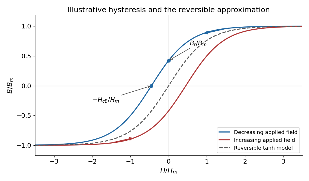
Magnetic hysteresis and the reversible tanh approximation
. Original illustrative magnetic hysteresis loop with the remanent magnetic field and normal coercive magnetic field strength marked. The dashed single-valued curve is the reversible approximation used in the calculation, rather than a hysteresis branch. Details.
Use the stated single-valued constitutive equation for the calculation. Inverting it gives , soSince , the small-signal response of a gapped magnetic core isThe small-field core magnetic permeability is . Strictly, is a reversible approximation: at it has , so it cannot itself model nonzero remanence. The displayed loop and this constitutive approximation serve different purposes. Keeping a genuinely remanent branch would generally add a history-dependent offset; it would not imply through the origin.
The coils form a mutual induction apparatus. Changing primary electric current changes secondary magnetic flux linkage . Faraday's law of induction givesOn closing the primary circuit, increasing electric current produces a transient secondary electric current and galvanometer deflection. By Lenz's law its direction opposes the increasing magnetic flux. Once primary electric current and core magnetization are steady, the derivative vanishes: the galvanometer returns to zero despite the continuing magnetic field.
On opening the circuit, the decreasing magnetic flux induces a secondary electric current tending to sustain that flux. The galvanometer deflects oppositely, then returns to zero. Making and breaking produce opposite transient deflections; steady primary current produces no sustained induced current.
For fixed linear coils, and , with mutual inductance . Opposite equal changes of primary electric current give opposite equal areas under the induced-electromotive force curves in that model. Peak sizes can differ with switching times. Real iron-core magnetic hysteresis and remanent magnetization can also change the flux excursion, so equality of the actual peaks is not required.
Mutual inductance expresses how a changing electric current in one circuit induces an electromotive force in another. Choose winding orientations and define their linked magnetic fluxes byFor a reciprocal linear magnetic system, the same appears in both expressions. Faraday's law of induction gives when the secondary electric current does not itself change. The sign depends on winding orientation and is consistent with Lenz's law.
The stored magnetic energy isIts nonnegativity for arbitrary electric currents requires . Strong coupling makes approach ; flux leakage makes it smaller.
An ideal electrical transformer has two windings linked by the same time-varying core magnetic flux. The induced winding voltages are proportional to their turn counts. For appropriately chosen terminal polarities,The electric current convention in the power relation takes primary power into the device and secondary power out to the load. Consequently a load electrical impedance appears at the primary as . A larger secondary voltage therefore comes with a smaller available secondary electric current, rather than extra energy.
A steady direct electric current produces no sustained transformer action after its switching transient. Practical departures from the ideal include winding electrical resistance, leakage magnetic flux, finite magnetizing electric current, core saturation, eddy currents and magnetic hysteresis losses.
A permanent magnet retains a substantial magnetization without an applied coil electric current. In a ferromagnetic material this reflects microscopic magnetic moments, magnetic domains and their resistance to rearrangement. The history-dependent relation between applied field and magnetization gives magnetic hysteresis, remanence and coercivity. A soft core used in an electromagnet or electrical transformer is chosen for easy magnetization and small hysteretic loss; a permanent-magnet material must resist demagnetization.[ref]
The Feynman Lectures on Physics, Volume II by Richard Feynman and others. Chapter 36, especially §36–3 and Figures 36–8 to 36–9: magnetization curves, remanence and hysteresis loss
The macroscopic fields obeyin magnetostatics. The magnetization can be represented by equivalent bound currents,Thus both permanent magnetic matter and free coil electric currents generate a magnetic field. Its magnetic field lines form continuous loops; apparent north and south poles are not isolated magnetic charges.
In a long ideal solenoid, . A linear core would give , until saturation or other nonlinear effects invalidate a constant magnetic permeability. In a finite magnetic circuit, air gaps and demagnetizing fields affect the field strongly: because the gap has low magnetic permeability, it often needs most of the available magnetomotive force. A permanent magnet can have a nonzero internal even when , because its boundaries create a demagnetizing field. Hence setting merely because there is no free coil electric current is generally incorrect.
Use a complex pair order parameter with signed charge , . A local isotropic Ginzburg-Landau theory of superconductivity has free energyFor , , the uniform amplitude is . Variation gives the static field equation and supercurrentThe vector potential obeys Maxwell's equations, including and , with and . The static approximation drops the displacement current. A common dissipative near-transition dynamical extension is the time-dependent Ginzburg-Landau equationIt is a phenomenological relaxation law in its applicable regime, not a universal microscopic Schrödinger equation for every superconductor. Its covariant time derivative and the covariant spatial derivative ensure consistent phase and electromagnetic gauge transformations.
The amplitude and screening lengths areFor the ideal model is type II. An Abrikosov vortex has a phase winding, a core with suppressed of size , and circulating screening currents over . Single-valuedness implies fluxoid and flux quantization in a superconductor:The sign of depends on the chosen circulation and charge convention. Far from the core, where the contour current term is negligible, each singly wound vortex carries one flux quantum in magnitude.
The equilibrium lower critical magnetic field marks favorable entry of the first vortex; for , with an order-one core correction . The upper critical magnetic field follows by linearizing the order-parameter equation in the field:Between these fields lies the superconducting mixed state, often with an Abrikosov vortex lattice. The ideal equilibrium entry and exit fields need not yield large irreversible loops. Flux pinning and surface barriers impede vortex motion; field sweeps then retain history-dependent flux and produce magnetic hysteresis and dissipative losses.
A superconducting weak link, such as a tunnel junction or narrow constriction, couples the phases of two superconductors. With consistent choices of phase and voltage orientation, the Josephson effect givesThe Gauge-invariant Josephson phase includes the line integral of across the link. A zero voltage can sustain a phase-dependent steady current; a constant nonzero voltage makes that contribution oscillate. Microwave irradiation can lock this oscillation to an applied frequency, giving voltage steps at , an experimental test of coherent pair transport rather than an ordinary resistive current law.
A DC SQUID places two weak links in a loop. For identical junction critical currents and negligible self-inductance, flux quantization fixes their relative phase difference to . Adding the two sinusoidal currents and maximizing over their common phase givesThe flux-periodic response provides sensitive magnetic measurements. Junction asymmetry or appreciable loop inductance changes the ideal contrast and can introduce additional hysteresis; the phase-coherent interference principle remains. The Jaklevic Josephson interference experiment is a motivating experimental realization of this link between a superconducting loop, weak links and magnetic flux.
Transformer (electrical engineering) Created 2026-10-18 Updated 2026-11-05
An electrical transformer transfers energy between electromagnetic coils through electromagnetic induction. A changing shared magnetic flux produces an electromotive force in each coil. In the ideal model, both coils link the same flux ; for and turns, Faraday's law of induction gives induced voltages proportional to and . Their relative signs depend on the winding orientations.[ref]
For sinusoidal operation, the ideal root mean square voltage magnitudes satisfyThe ideal lossless model also conserves transferred power. With negligible excitation electric current, its electric current magnitudes obey . For a load electrical impedance , combining the voltage and electric current ratios gives the input electrical impedanceThus an electrical transformer changes the voltage-current relationship seen by a source as well as the voltage.[ref]
University Physics Volume 2 by Samuel J. Ling and others. Section 15.6, equations 15.20–15.22; impedance formula derived here
For an ideal 10:1 turns ratio, a 230 V sinusoidal input produces 23 V at the secondary. A 23 ohm resistive load draws 1 A, corresponding to 0.1 A at the primary: both sides transfer 23 W. These are ideal-model calculations. Winding electrical resistance, magnetic hysteresis, eddy currents and incomplete shared flux introduce losses or departures from those ratios in a real electrical transformer. A constant flux produces no sustained induced secondary voltage.