With phasors proportional to , the series RLC circuit hasFor fixed and frequency-independent positive , the maximum occurs when the reactances cancel. ThusThis is the driven current resonance; a damped free-oscillation frequency is a different quantity.
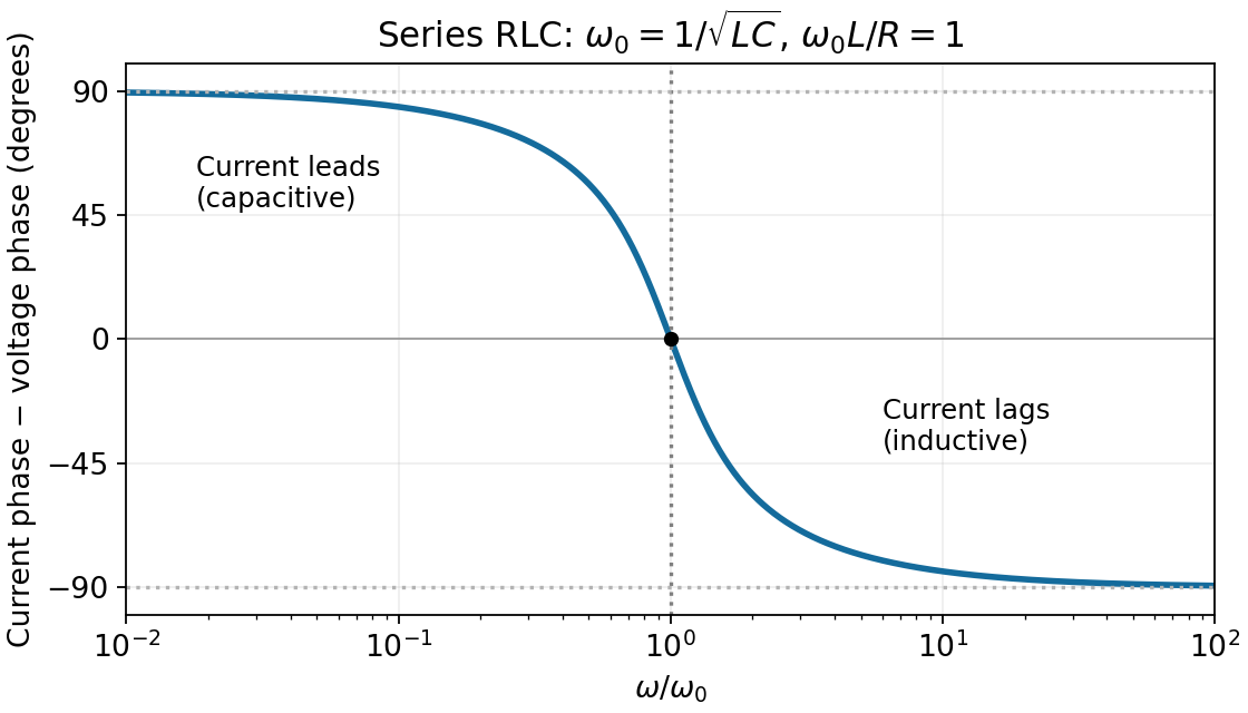
Define the phase difference as current phase minus voltage phase. Since ,It decreases continuously from at low frequency, through zero at , to at high frequency. Thus the current leads in the capacitive limit and lags in the inductive limit. Defining voltage phase minus current phase would reverse the graph's sign.

Articles by others on the same topic
There are currently no matching articles.