For a lossless antireflection coating, cancellation requires both equal reflected wave amplitudes and an odd half-cycle difference in their round-trip wave phase. At normal incidence the interface amplitude coefficients are and . Choosing makes both negative: both reflections acquire the same phase reversal. A quarter-wave optical thickness supplies their remaining relative phase .
Equal amplitudes require , which reduces to . ThusThe exact multilayer reflection amplitude is zero for these choices, not merely the sum of the first two reflected rays: its numerator is , with . Any positive odd multiple of this thickness has the same cancellation at the design wavelength; the smallest is the thin-layer choice. absorption, index dispersion, angular spread and deviations from the selected wavelength limit the practical cancellation.
A Fresnel zone plate replaces a conventional refracting surface by concentric alternating transmitting and absorbing annuli. Successive annuli span half a wavelength of optical-path excess to the chosen focus; blocking alternate zones prevents their approximately opposite wave phases from cancelling. For a normally incident plane wave,The paraxial radii grow as , so the zones become narrower outwards.
Using the photon energy relation gives . For ,The first three boundaries are approximately , and . This fixes the zone pattern but does not fix a unique outside diameter: the number of zones is a design choice. For example, gives radius , diameter and outermost zone width about . A larger usable diameter requires finer outer zones.
One could pattern absorbing metal annuli on a thin X-ray-transparent support, choosing absorber thickness from its attenuation at the selected photon energy; that thickness cannot be determined from energy and focal length alone. The design is chromatic: for fixed radii , so a narrow energy band is needed for a sharp common focus.
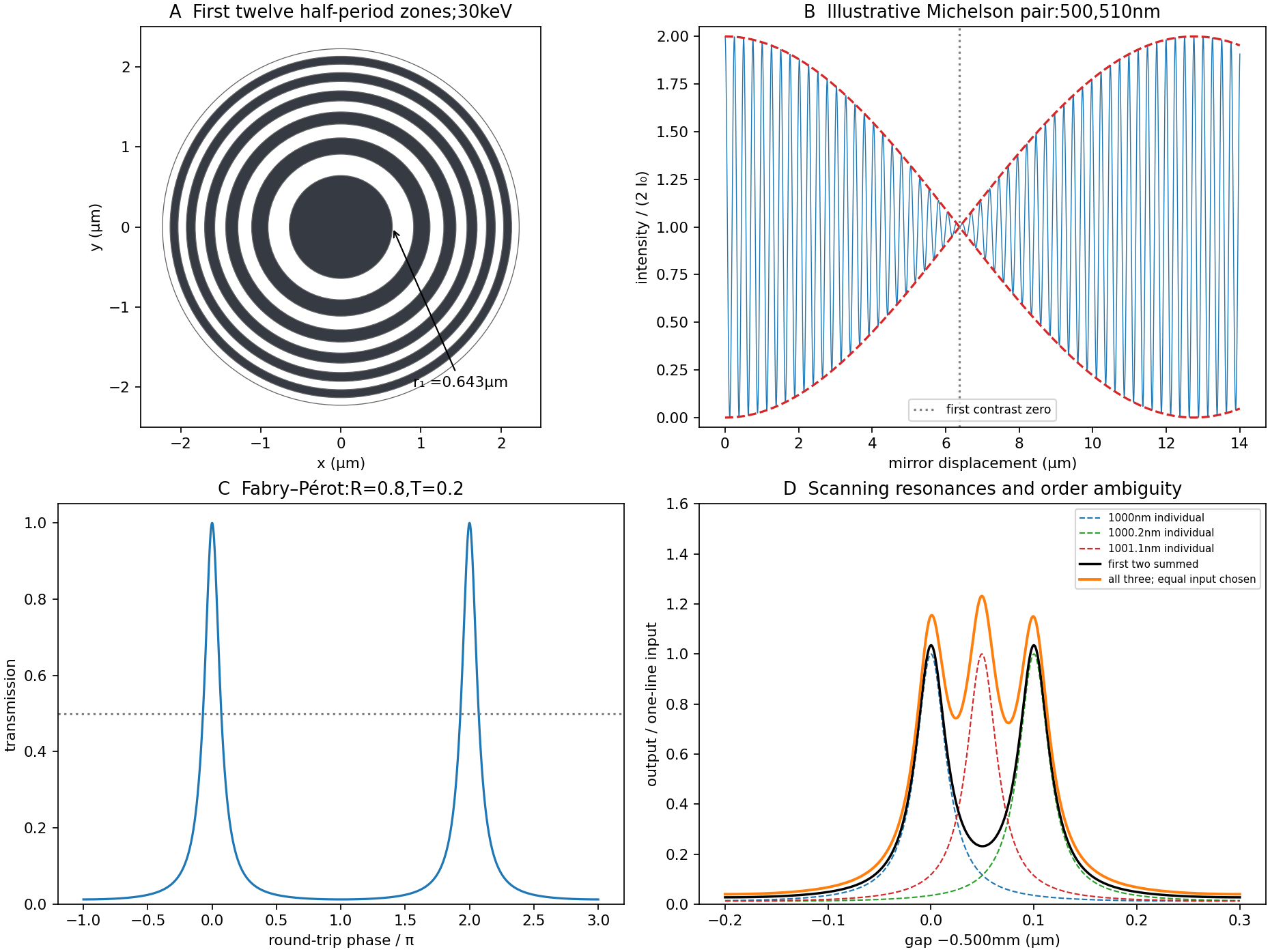

Let be mirror displacement from equal optical paths in a Michelson interferometer, so the optical path difference is . Different spectral components add detected light intensities; each component interferes with its own delayed copy. For equal line strengths and ideally balanced arms, writeThe trigonometric identity for the sum of cosines givesThus the sketch consists of rapid fringes within a slowly varying contrast envelope. With the mean wavelength and , the mirror-displacement fringe spacing is . The interference visibility isThe first contrast zero is at ; successive visibility maxima are separated byBetween successive contrast zeros the signed envelope changes sign, shifting the rapid fringes by half a cycle. Unequal line strengths leave a nonzero minimum contrast. Finite linewidth adds a longer-range coherence envelope, while arm imbalance and polarization mismatch can reduce contrast without indicating a different spectral spacing.
Use periodic boundary conditions temporarily to count the allowed wavevectors. Each state occupies in reciprocal space. For one acoustic polarization, the spherical shell between and containsBoth positive and negative wavevector directions are already included in that sphere; no further factor of two is needed. With the linear dispersion relation ,A three-dimensional monatomic crystal has three acoustic branches. Under the stated common-speed approximation,This is a phonon density of states per unit angular frequency, not per unit ordinary frequency. If longitudinal and transverse speeds differ, the isotropic expression becomes . In the Debye model, imposing sets the cutoff; the linear approximation is not continued to arbitrarily high frequency in a finite lattice.
The effective mass follows from the curvature of the electronic band structure. Differentiating twice givesAt either first Brillouin zone boundary ,The boundary is a band maximum, with negative curvature and zero group velocity. In the semiclassical single-band description, an applied force changes ; the resulting acceleration is opposite the force near that maximum. This is a band-response coefficient, not a negative microscopic electron rest mass. A nearly filled band is often described more conveniently through positively charged electron holes near its maximum.
Articles by others on the same topic
There are currently no matching articles.