In Fraunhofer diffraction, the relative propagation phase across the aperture is linear in aperture coordinates. If is its largest transverse size, the neglected quadratic path term must be small: for an observer at distance ,For a finite-distance point source a distance away, also require if the illumination is to be treated as a plane wave. Numerical factors depend on whether is a radius or full width and on the permitted phase error; the condition expresses a small Fresnel number.
One can place both source and screen sufficiently far away, or collimate a point source with a lens and observe the aperture in the back focal plane of a second lens. In the latter arrangement rays of each outgoing direction focus at one point, with ; the lens removes the need for a physically distant screen. A laser beam approximately uniform across the aperture can supply the incident plane wave. The sketches distinguish an actual far field from its focal-plane equivalent.
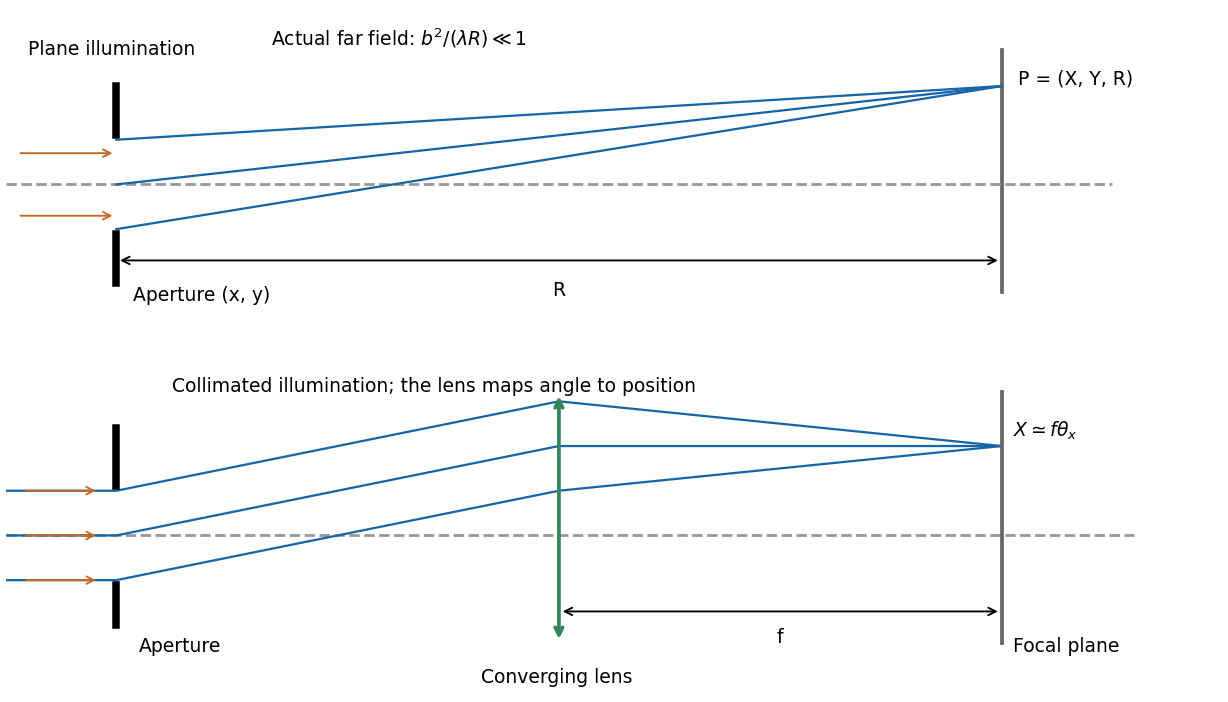
Let the aperture occupy the plane, with coordinates and opening . Write for the incident scalar complex amplitude and for its dimensionless amplitude transmission, including any imposed phase. The observation point has transverse coordinates , corresponding to the PDF's , and axial distance . Also is the wavenumber and .
The Huygens-Fresnel principle expresses the propagated field, up to common prefactors and an approximately constant obliquity factor, asIn the paraxial approximation, expand the path asThe last term is negligible in the Fraunhofer diffraction limit, while the first two terms and are common across the aperture. Factoring them out leavesIt is the two-dimensional Fourier transform of the transmitted aperture field, evaluated at transverse wavevector . For appreciable observation angles the corresponding exact directional components are used rather than .
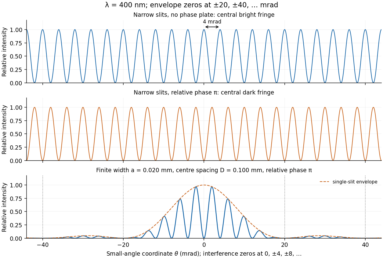
Represent equal narrow slits at by two contributions with equal complex amplitudes. In a direction the path difference is , soTherefore double-slit interference givesThe bright interference fringes satisfy , with a central maximum. In the small-angle region,Dark fringes lie halfway between bright ones. Exactly, spacing is uniform in , not in at large angles. The first panel of the pattern figure below shows the narrow-slit result.
A relative phase changes the sign of one slit field. Their sum becomesThe central interference fringe is now dark. The maxima move to , while the minima occur at . Thus the pattern shifts by half a fringe, near the axis, but its angular fringe separation remains . This assumes the glass changes phase uniformly and introduces negligible absorption or beam deflection.
For a rectangular slit centred at , the one-dimensional Fraunhofer diffraction integral isThe two equal apertures have centres at ; the glass subtracts their fields. ThereforeThis is phase-reversed double-slit diffraction: the narrow-slit interference factor is multiplied by the single-slit diffraction envelope. In the limit , the normalized envelope tends to one, recovering part (d).
The interference minima and envelope minima obey, respectively,Near the axis these are and envelope zeros . Here , so every envelope zero already coincides with an interference minimum. The envelope strongly reduces the outer fringes; its central value is nonzero, but the total intensity still vanishes at because the two fields cancel. The sketch uses the small-angle coordinate; the equations above specify the exact angular zeros.


Articles by others on the same topic
There are currently no matching articles.