In sinusoidal steady state, complex impedance is the voltage phasor divided by the current phasor. Its modulus is the amplitude ratio and its argument is the voltage lead. With the convention, , so .
The PDF labels across , not across the complete driven network. If is the current through , then and , whereThe resistor-referenced parallel-resonator response isWriting ,The maximum occurs at , where and the phase is zero. Below resonance the phase is positive, tending to ; above it the phase is negative, tending to . The amplitude tends to zero at both extremes: the inductor shorts the parallel network at low frequency, and the capacitor does so at high frequency. At resonance their reactive currents cancel, leaving only the resistor current.
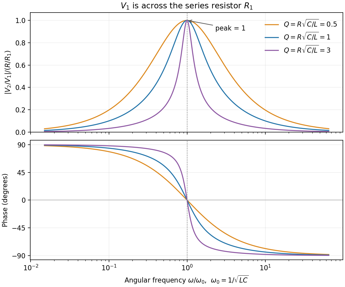
Resistor-referenced parallel-resonator amplitude and phase, normalized without choosing circuit component values
. Details. 
If instead denotes the voltage across the complete circuit, its different transfer ratio is , with peak . This distinction follows directly from the printed voltage endpoints.
For free parallel RLC voltage decay, measure and branch currents from A to B. ThenThere is no external current, so Kirchhoff's current law gives . Differentiating yieldsFor the characteristic equation is . Its underdamped roots giveThe supplied inequality makes real. A real physical voltage has the general form , the real part of the printed complex expression. A general complex-valued solution uses both roots, . The inductor's initial current is fixed consistently by the undifferentiated current balance; it is not an arbitrary additional voltage-mode constant.
Articles by others on the same topic
There are currently no matching articles.