The original diagram places the output across the resistor, in series with an ideal inductor. Treat the voltages as phasors with time dependence . The electrical impedances are and , so the same electric current flows through both:This is an RL low-pass filter, with corner angular frequencyThe frequency response tends to one for , has magnitude at the corner, and tends to for . The requested sketch uses a logarithmic horizontal axis and a linear voltage-gain axis:
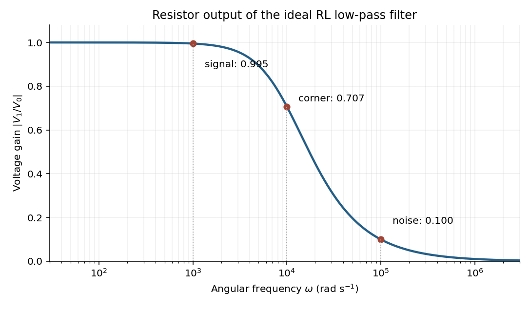

At the two specified angular frequencies,The relative attenuation by a linear filter is the ratio of these gains:Thus the noise amplitude is attenuated by a factor of 10 relative to the signal. A squared-voltage ratio would decrease by a factor of ; the question's voltage transfer function gives the amplitude comparison.
Articles by others on the same topic
There are currently no matching articles.