Use three positive-edge-triggered D flip-flops, all driven by the same clock signal . Write the current binary representation as , with the least significant bit. The next state is the current value plus one when and minus one when , in each case modulo eight. A bit toggles under exclusive or with a one.
For upward counting, toggles when , while toggles when , the respective carry conditions. For downward counting the corresponding borrow conditions are and . Define the shared inverted direction and the two direction-match signalsEach is one exactly when : it equals for upward counting and for downward counting. Thus the Boolean functions for the three D inputs areImplement this with two NOT gates for , four two-input exclusive or gates for , and one two-input AND gate. Connect to the D flip-flop whose output is ; feed the three outputs back into the indicated gates. All three flip-flops capture simultaneously, so each equation uses the old state.
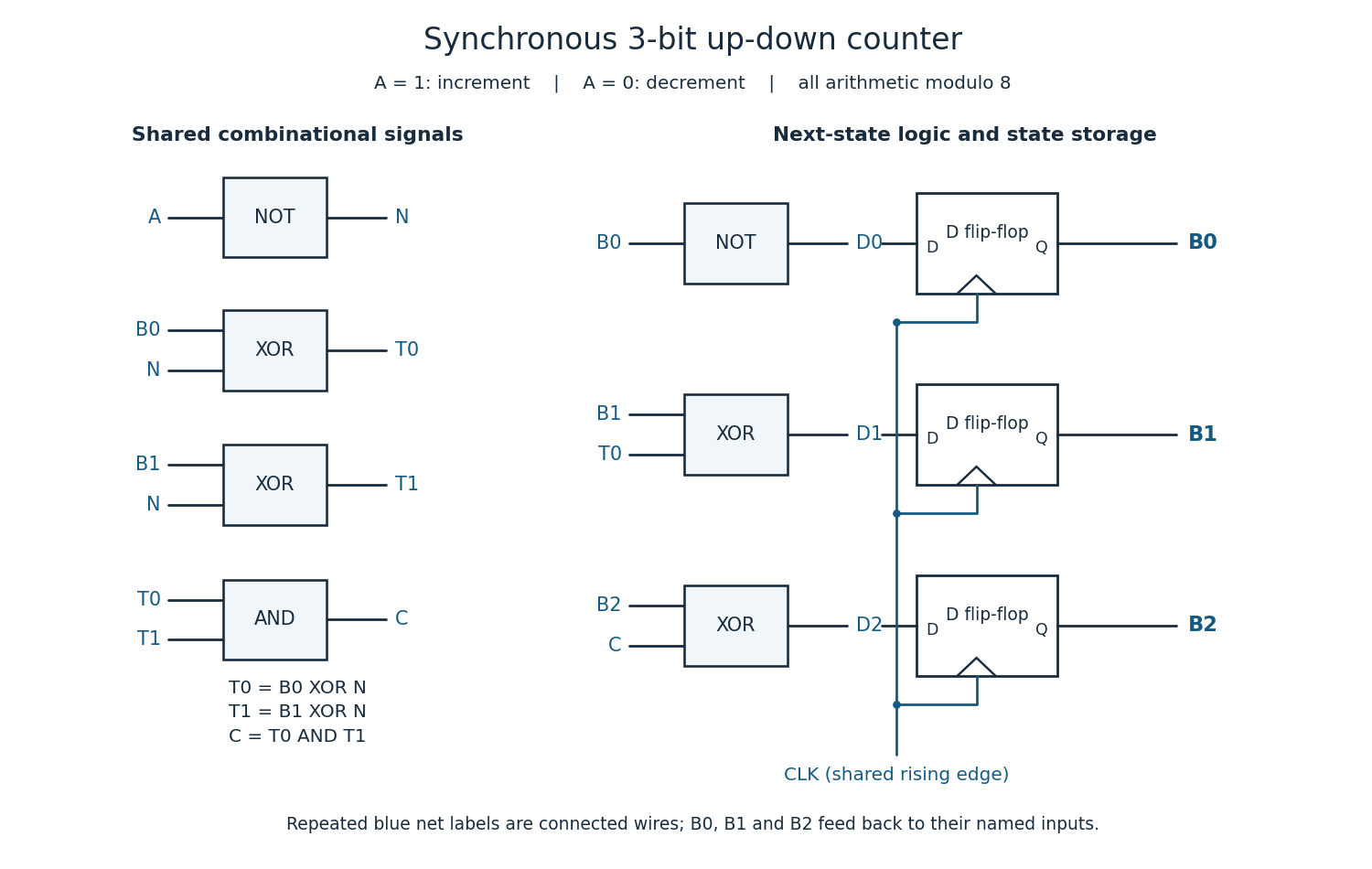

For completeness, the state transition table is
| Current | Next for | Next for |
|---|---|---|
000 | 001 | 111 |
001 | 010 | 000 |
010 | 011 | 001 |
011 | 100 | 010 |
100 | 101 | 011 |
101 | 110 | 100 |
110 | 111 | 101 |
111 | 000 | 110 |
Every three-bit state is valid. A reset may initialize the binary counter to zero if required; counting itself needs no extra state. The direction input must meet the setup time and hold time requirements at the active clock edge.
Articles by others on the same topic
There are currently no matching articles.