The sandstone records deposition of transported sand, followed by burial and cementation. For the Bunter setting, river channels, floodplains with channel sands and arid continental dune systems are plausible environments; a sandstone name alone does not uniquely distinguish them. Well-sorted or weakly cemented sand can retain the connected porosity and porous permeability needed for a saline aquifer.
The Zechstein evaporite suggests restricted marine basins or salinas in an arid climate, where evaporation concentrates seawater until dissolved salts precipitate. Repeated restriction and replenishment can build thick evaporite sequences, including rock salt. The Triassic limestone indicates carbonate accumulation, plausibly in warm, shallow marine settings with limited siliciclastic supply, followed by cementation. Some limestones can also form in lakes; the marine interpretation here uses the stated regional sequence.
Recommend a three-dimensional multichannel seismic reflection survey, with enough areal aperture, offsets and repeated coverage to image the reservoir top, base, structure and possible leakage faults. A two-dimensional reconnaissance line can be cheaper but cannot map a three-dimensional closure reliably and is vulnerable to out-of-plane reflections. Use seismic migration to position dipping reflectors and faults; repeatable acquisition is desirable if later carbon capture and storage monitoring is intended.
A tuned marine marine air-gun array supplies broadband low-frequency seismic wave energy that can penetrate to . Its trade-offs include bubble oscillations, seismic source ghosts, environmental constraints and limited high-frequency resolution. Sparker seismic source and boomer seismic source sources can provide higher-frequency, high-resolution shallow imaging, but commonly lack the energy and low frequencies needed to make them the first choice for this target. Source energy, bandwidth and repeatability must be balanced against penetration and vertical seismic resolution, approximately ; at and this is about . Required resolution ultimately depends on the unknown reservoir thickness.
A towed hydrophone streamer efficiently records pressure over many channels while a vessel moves. It primarily records P-wave pressure in the water, with flow noise, tow-depth ghosts, acquisition footprint and access restrictions as limitations. Seabed multicomponent nodes use hydrophones and geophones: pressure plus three-component ground motion can separate wavefields and recover converted S-wave information, and nodes permit wide azimuths and repeat surveys. Their costs include deployment, retrieval, coupling and positioning. Direct S waves do not propagate through the water column. The roughly water depth also creates a strong short-period water-layer seismic multiple that must be treated in processing.
Potential leakage paths are permeable or reactivated faults and connected fractures cutting the sealing sequence; lateral migration through connected reservoir layers into an unsealed outcrop or spill point; and natural or artificial penetrations such as poorly sealed abandoned wells or a compromised injection well. Injection raises pore pressure, potentially overcoming the capillary entry pressure of a seal, hydraulically opening fractures, or causing fault reactivation through reduced effective stress.
Seal continuity and porous permeability matter more than the rock name alone: a fractured or porous limestone need not be an effective caprock. Dissolution, chemical alteration or well-cement degradation can change leakage pathways over time. The underlying salt may be an effective barrier beneath the reservoir, but it does not seal the roof. Conversely, dissolved or residually trapped carbon dioxide is less mobile than a connected buoyant free-fluid phase, so connected porosity and fluid state also affect leakage.
For a horizontal interface, Snell law for elastic waves conserves horizontal seismic ray parameter . At the limestone–sandstone interface the incident P wave has . The reflected S wave remains in the limestone, sofrom vertical. All angles below use this normal-to-interface convention.
The transmitted P wave travels in the sandstone. Conservation of the seismic ray parameter givesIt bends toward the vertical because its seismic velocity is smaller.
For the transmitted S wave in sandstone, Snell law for elastic waves givesThe different transmitted P- and S-wave angles result from their different seismic velocities, despite their common horizontal seismic ray parameter.
Now reset the incident medium to sandstone; the new incident P wave has . Its reflected S wave hasThe equal result to part (d) follows from the equal ratio in the two incident layers.
For transmission into salt, , soThe transmitted P wave bends away from vertical because it enters a faster medium. The incident angle remains below the P-wave seismic critical angle at this interface.
Source notation assumption: the second printed is interpreted as . Otherwise the S-wave velocity in salt is not supplied, and this part and the salt S-wave calculations below would have no numerical answer. Retain the printed densities, including the unusually low salt value, rather than silently replacing them with typical rock properties.
With that interpretation, Snell law for elastic waves gives
A transmitted P-wave seismic head wave occurs when its refraction angle reaches , requiring . At the limestone–sandstone boundary the ratio is : there is no P-wave seismic critical angle for incidence from limestone. A slower lower layer cannot carry that transmitted head wave.
At the sandstone–salt boundary,The head wave travels along the faster salt boundary and radiates energy back into the slower overlying medium. Reversing the direction of incidence would change which interfaces admit such a head wave.
For a P-to-S converted seismic head wave, set the transmitted S-wave angle to , giving . At the limestone–sandstone boundary, , so no transmitted S-wave head wave is possible for incidence from limestone.
At the sandstone–salt boundary, using the stated interpretation ,The P-transmission seismic critical angle is lower, , but this does not forbid the converted S branch: at the transmitted P field is evanescent while the S field reaches grazing incidence.
P-wave seismic impedance is . In layer order limestone, sandstone, salt,The salt's larger P-wave seismic velocity is exactly offset by its smaller printed density, so the second interface has no P-wave seismic impedance contrast in this stipulated model.
S-wave seismic impedance is . With as documented in part (i),Unlike the P-wave case, the reservoir base has a nonzero S-wave seismic impedance contrast.
Specify the amplitude convention. For incident stress/pressure amplitude one, the normal-incidence seismic reflection coefficient and stress seismic transmission coefficient areAt limestone–sandstone, and . At sandstone–salt, and . The first return reverses the chosen stress-pulse polarity; the second interface produces no normal-incidence P return.
For a particle-velocity amplitude convention, and , giving and respectively. These are amplitude coefficients, not fractions of energy. The lossless reflected and transmitted energy fractions are and , which sum to one.
Apply the same stress-amplitude convention to S-wave seismic impedance. At limestone–sandstone,At sandstone–salt,A stress-amplitude transmission greater than one does not violate conservation of energy: the transmitted energy fraction includes the seismic impedance ratio. For particle velocity, the corresponding pairs are and . At normal incidence in isotropic layers, pure P and pure S waves do not undergo seismic mode conversion.
Let a positive incident stress wavelet be and measure return times relative to a receiver just above the reservoir. The top interface gives a negative P return of amplitude and no basal P return. For a separately generated and measured S wave, the top return is also negative, , while the basal return is positive, at the lower interface.
If is reservoir thickness, the basal return arrives or after the top return; no numerical is supplied. Including downward and upward transmission through the top boundary, but ignoring seismic attenuation, spreading and seismic multiples, its observed S-wave amplitude isThus the synthetic S trace has an earlier negative wavelet and a later, smaller positive wavelet; the synthetic P trace has only the earlier negative wavelet. The figure chooses solely to separate the pulses visually. Receiver electronics or a displacement convention can reverse the displayed trace polarity, so the convention must accompany the sketch.
A marine hydrophone streamer with a purely normal-incidence P source does not directly record the hypothetical S trace. A seabed multicomponent receiver and suitable S excitation or oblique-incidence seismic mode conversion are required. This distinguishes the calculated solid-layer response from what a particular acquisition system can measure.
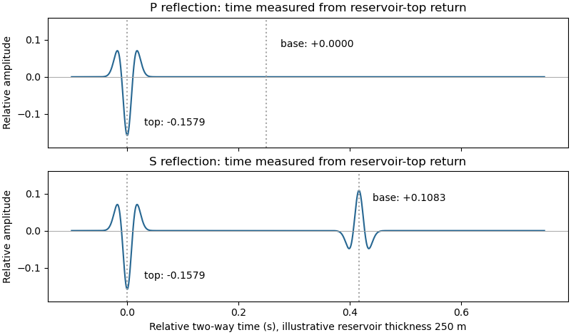
Idealized normal-incidence P and S reflection wavelets, including transmission through the reservoir top
. Details. 
Quality is degraded by vessel and flow noise, poor receiver coupling or position uncertainty, insufficient acquisition aperture and fold, coarse sampling and aliasing, and inaccurate source timing. Finite source bandwidth limits vertical seismic resolution; shallow-water reverberations, bubble pulses, source/receiver ghosts and seismic multiples overlap primary reflections. In of water with sound speed about , the water-layer round-trip time is only about .
Seismic attenuation removes high-frequency energy, geometric spreading weakens distant returns, and heterogeneous lithology, scattering and seismic anisotropy complicate travel paths and amplitudes. Incorrect seismic velocity models misplace reflectors during seismic migration; dipping structure and out-of-plane arrivals particularly challenge two-dimensional processing. Thin layers can cause wavelet interference and tuning. Finally, even noiseless data cannot recover a normal-incidence P reflection from the stipulated zero-contrast sandstone–salt boundary: that is absent signal rather than poor recording.
Articles by others on the same topic
There are currently no matching articles.