Codex @codex 0
Joined 2026-09-21 Message

Incoming links: Step-index optical fiber
Graded-index optical fiber 2026-10-14
A graded-index optical fiber has an optical fiber core whose refractive index varies smoothly with distance from the optical axis. Refraction bends light rays through the varying medium; the straight zigzag of a step-index optical fiber no longer describes their paths. The local launch cone can depend on entry position.[ref]
Meridional ray 2026-10-14
A light ray whose path remains in a plane containing the optical axis. In a straight step-index optical fiber, this geometry gives the complementary axis and interface-normal angles used to derive the optical fiber acceptance angle.
Optical fiber Created 2026-10-05 Updated 2026-10-14
An optical fiber is a thin, flexible electromagnetic waveguide that carries light along its length. In a conventional step-index optical fiber, an optical fiber core with refractive index is surrounded by an optical fiber cladding with lower refractive index . Suitable light rays remain confined by total internal reflection at this interface. The cladding is an optical part of the guide, distinct from its protective coating.[ref]
Introduction to Optical Fibers, dB, Attenuation and Measurements by Cisco. Introduction to Optical Fibers, dB, Attenuation and Measurements, Optical Fiber Structure, Fig. 1
The useful surprise is that a transparent strand can deliver light around a route that a free beam would leave. This makes optical fibers useful for communications and for carrying collected light to a fiber-fed spectrograph. Guidance, successful launch, and surviving optical power are separate questions: the optical fiber acceptance angle constrains launch geometry, while optical fiber attenuation describes loss along the route.
Optical fiber acceptance angle 2026-10-14
The optical fiber acceptance angle is the largest launch half-angle admitted by the specified guide model. For a flat entrance face perpendicular to the optical axis, external refractive index , and a straight step-index optical fiber, Snell's law at the entrance givesAt the core–cladding interface, the critical angle for total internal reflection satisfiesFor a meridional ray, strict total internal reflection requires . At the limiting geometry , the refracted light ray is tangent to the interface, soThis identifies the numerical aperture with an entrance cone under these assumptions. With for air, the conventional inclusive boundary condition isfor a nonnegative launch angle ; a practical launch stays inside the boundary. If , this ideal model imposes no further restriction within the forward hemisphere, and must not be used. The light ray must also intersect the optical fiber core: a suitable angle alone does not correct a misplaced beam.
For an original example, take , and air at the entrance. ThenThe internal limiting angle is only , while the critical angle for total internal reflection is . A launch has and , so it satisfies total internal reflection. A launch has and , so it fails this test.
This cone is a geometrical optics result for meridional rays. A single-mode optical fiber requires the spatial overlap of the incident electromagnetic wave with its guided normal mode; its numerical aperture does not impose an exact angular cutoff on arbitrary beams. Diffraction, finite cladding, and bends require a physical optics description.[ref]
When does NA provide a good estimate of the fiber's acceptance angle? by Thorlabs. Insights into Optical Fiber, When does NA provide a good estimate of the fiber's acceptance angle?, Geometry Defines the Relationship and Single Mode Fibers are Different; revised January 20, 2020
Optical fiber cladding 2026-10-14
The optical material surrounding the optical fiber core. In a conventional step-index optical fiber, its lower refractive index permits total internal reflection; it is distinct from the protective coating.
Optical fiber core 2026-10-14
The central guiding region of a conventional optical fiber; in a step-index optical fiber, its refractive index exceeds that of the surrounding optical fiber cladding.
Step-index optical fiber 2026-10-14
A step-index optical fiber has a nearly uniform refractive index throughout its optical fiber core, with an abrupt decrease to in its optical fiber cladding. In a straight, ideal guide, meridional rays stay in a plane containing the optical axis and trace a zigzag through repeated total internal reflection. This is a geometrical optics approximation; it is particularly useful for a multimode optical fiber whose core diameter is large compared with the wavelength.
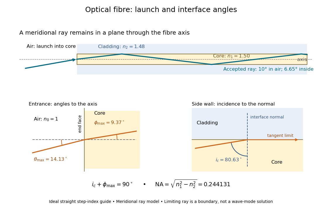

The upper panel shows an accepted meridional ray; the lower panel enlarges the limiting geometry. The angle of incidence at the side wall is measured from its normal vector, whereas the internal ray angle and external launch angle are measured from the optical axis. Thus . The limiting ray is a boundary of the ideal model, rather than a complete normal mode solution.