A real voltmeter has finite input electrical resistance ; a galvanometer also has a finite winding electrical resistance. Away from balance, its electric current changes both intermediate electric potentials. This is voltmeter loading when the detector is a voltmeter. Model the detector as a passive resistor, with no offset or injected electric current. Thévenin's theorem supplies the full response without pretending the connected bridge remains two independent voltage dividers.
With the detector removed, the equivalent source is . Replace the ideal supply by a wire to calculate the source electrical resistance seen between : nodes merge, making parallel and parallel. ConsequentlySince the attenuation factor is strictly positive for , the null remains . A smaller detector electrical resistance reduces the measured electric potential difference off balance but does not shift the ideal null. Its electric current sensitivity instead depends on ; detector gain and resolution also matter in deciding how closely a null can be located.
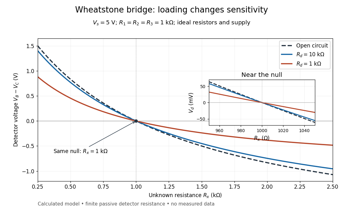
Finite detector resistance reduces bridge voltage sensitivity while preserving the null
. Calculated curves use and . All cross zero at ; the inset resolves their different slopes. These curves are a model, not measured data. Source. Details.
In the plotted example, gives and . A detector with instead reads . Using that loaded reading in the unloaded voltage divider formula would underestimate the deviation of from . Balancing the bridge avoids this particular systematic measurement error.
The local derivative makes the sensitivity explicit. For and , the first-order Taylor expansion isAt the plotted null, the open-circuit slope is , compared with for . Increasing the supply improves this ideal sensitivity but also increases Joule heating. A finite source electrical resistance requires recomputing ; the displayed parallel-pair expression assumes an ideal supply.
Articles by others on the same topic
There are currently no matching articles.