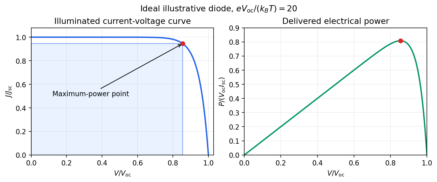
Keep the illumination and cell temperature approximately constant. Connect an ammeter and an adjustable resistor as a series circuit across the solar cell; connect a high-resistance voltmeter across its terminals. Vary the electrical resistance and record pairs of electric potential difference and delivered electric current . This measures the illuminated current-voltage characteristic.
A load close to a short circuit estimates at . With the load disconnected, an open circuit measurement using a high-resistance voltmeter estimates at . Neither endpoint delivers useful power: vanishes there. The intermediate readings locate the maximum of and determine the solar-cell fill factor. Holding illumination fixed matters because the photogenerated electric current changes with light intensity; holding temperature fixed matters because the diode saturation current and junction response change with it.
This experiment distinguishes producing an electric potential difference from delivering energy to a load. To determine conversion efficiency as well, measure the incident power on the illuminated area, rather than equating it to a lamp's electrical rating.

Articles by others on the same topic
There are currently no matching articles.