For a current element , the Biot-Savart law isTake a straight wire along , extending from to , and observe its magnetic field at . All contributions point in for positive along , by the right-hand rule. Their magnitude integrates toFor this becomes , so , exactly as Ampère's law requires for an infinite straight wire.
Each long wire lies in the other's magnetic field, . The magnetic Lorentz force per unit length has magnitudeFor the two-wire circuit's self-inductance, a nonzero wire radius is essential. Introduce a radius . Between the wires their magnetic fields add. The external magnetic flux linkage per unit length through the connecting ribbon is, to leading order in ,It follows that the leading thin-wire loop self-inductance per unit length isIt is the loop value for the pair, not the contribution of just one conductor. Corrections from the wire interior depend on the current distribution: for nonmagnetic round wires with uniform direct electric current, the pair contributes another ; for a surface current the internal contribution is zero. The leading logarithm is common to both models.
TODO (source data): the source gives no wire radius or current-distribution convention. There is no finite radius-independent value of the requested self-inductance: taking ideal zero-width wires sends to infinity. The force and the parameterized leading self-inductance above are determined, but a unique finite answer requires that additional specification. For example, changing to changes the leading result by even at fixed separation.
Put the three wires at with and each current along , out of the page. Adding their Biot-Savart law magnetic fields givesFor , all three -components have the same sign, so they cannot cancel. On , a zero of the remaining component satisfiesExcluding the wire positions themselves, the two and only two finite zeros areThe magnetic field lines circulate counterclockwise about each current near that wire. Far away they circle the combined total current . The two nulls separate the nearby circulation regions in the original magnetic field line plot below.
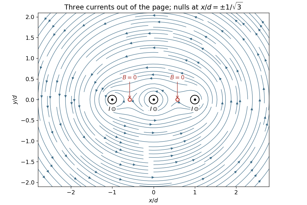
Magnetic field and two nulls for three equal parallel currents
. Coordinates are measured from the middle wire in units of the neighbouring-wire spacing. All three currents point out of the page; the two field zeros are marked between the wires. Details.
For a displacement of the middle wire, the horizontal attractions towards the two fixed outer wires cancel. Each attraction has magnitude per unit length. Projecting them in the direction givesNeglecting dissipative effects and other transverse forces, this is simple harmonic motion. Release from rest at givesThe inverse-angular-frequency timescale is ; it differs from the oscillation period by . The assumed displacement plane matters: small displacements towards one outer wire along are unstable, rather than oscillatory.
This result concerns the specified magnetic motion with gravity absent from, or compensated in, the direction. The source diagram fixes coordinate directions, not their orientation relative to gravity. If is physically vertical with upward positive and the wire is unsupported, add to the force per unit length. The maximum restoring magnetic force is only , compared with weight ; that different setup would fall and could not oscillate about the original plane.
Articles by others on the same topic
There are currently no matching articles.