Source paper: www.whatdotheyknow.com/request/physics_preliminary_past_papers/response/2680788/attach/2/2014%202017%20Physics%20Prelim.zip?cookie_passthrough=1. The cover dates this ordinary CP2 paper to 6 June 2017; the archive member's directory name is not the examination year. Unlettered blocks in the longer questions are indexed a, b, and so on. All four longer-question options are treated. The missing wire-radius specification is identified in 9b.
Let , where , and let be the incident electron speed. Nonrelativistically, . Take the plate length along the beam as , their separation as , and their centre-to-screen distance as . A signed deflecting voltage gives the transverse acceleration , choosing its sign so that positive deflects the electron towards positive . The transit time is . The displacement inside the plates and in the subsequent field-free drift isThus the two screen edges requireThe transverse deflection at plate exit is at either extreme, smaller than the half-gap , so the beam clears the plates. The outgoing slope is ; no small-angle replacement for the trajectory was used. The kinetic energy remains far below , so the nonrelativistic approximation is adequate. If “30 cm behind” is instead measured from the downstream plate edge, replace by , giving approximately ; the intended thin-deflector estimate is about .
Orient the ring's area normal with positive external magnetic flux. Faraday's law gives the applied electromotive forceThe ring's self-inductance opposes changes in its electric current. With positive electrical resistance , Kirchhoff's voltage law therefore gives . Define . The periodic steady state isThe second result follows from Joule heating, , and . For unspecified initial conditions, add a transient ; the displayed time average is over the periodic steady state after that transient has decayed. The inductor temporarily stores and returns energy, with no net storage change over one complete cycle.
Use a cross-section normal to the sheets' line of intersection: the positive sheet is , and the negative sheet is . A Gaussian pillbox gives a single infinite sheet's electric field magnitude on either side. Superposition consequently gives, away from the sheets,The electric field points away from the positively charged sheet and towards the negatively charged sheet, bisecting each right angle. The electric field lines are straight within each quadrant: in the first quadrant, for example, , so is constant along a line. They start on and finish on . At a sheet, the normal component has the usual surface-charge jump, so the quadrant formula specifies the appropriate one-sided limits rather than a unique electric field on the charged surface.
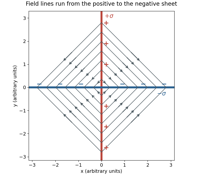
Cross-section of the electric field between perpendicular oppositely charged sheets
. Each arrow starts on the positive sheet and terminates on the negative sheet; the diagram is an original schematic of the derived field. Details.
The six faces subtend equal solid angles at the central point charge. Gauss's law fixes their total outward electric flux at . By the cube's symmetry,For negative the same signed expression represents inward electric flux. The result is independent of the side length.
Place eight identical cubes around the charged corner to make one larger cube, with the point charge at its centre. Each large face has electric flux and consists of four equivalent small faces. Each of the original cube's three faces opposite the charged corner therefore hasOn each of its three faces containing the corner, the electric field of the point charge obeying Coulomb's law is tangent to the face at every regular point; its outward-normal component is zero. Defining the face integral by omitting the singular corner givesA boundary point charge does not satisfy the ordinary nonsingular hypotheses for simply counting it as an interior charge in Gauss's law. The result expresses the octant solid angle and the specified improper surface integrals. Moving a charge towards the corner from inside a cube before integrating is a different limiting operation; its total closed-surface electric flux stays until it reaches the boundary.
In source-free vacuum, Maxwell's equations readTake the curl of the third equation and use the curl of the curl identity . ThenThe prescribed plane wave travels in the direction. Its polarization is along , and Faraday's law requires with . The wave's magnetic flux density is thereforeThe direction is also fixed by pointing along the propagation direction. A superposed static uniform magnetic field is not fixed by the oscillatory electric field; the expression above is the magnetic field belonging to the wave itself.
The requested source-image relation is the thin lens equation, using positive real-object distance and signed image distance :Here for a converging lens, and denotes a virtual image. This is usually distinguished from Lensmaker's equation, for a thin lens in air with the usual signed surface radii. The latter relates focal length to the lens material and curvature, rather than to object and image positions.[ref]
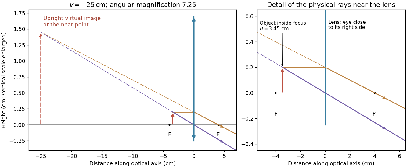
For a magnifying glass held close to the eye, compare the angle with the unaided near-point angle , where . Maximum usable angular magnification occurs with the virtual image at the near point, so . ThusThe object lies inside the front focal length. The emerging light rays diverge, while their backward extensions meet at an upright enlarged virtual image on the object's side. With the image at infinity instead, the relaxed-eye angular magnification would be , which is smaller. A finite eye-to-lens distance changes the near-point result to ; the quoted maximum uses the conventional limit.[ref]
University Physics Volume 3 by Samuel J. Ling and others. §2.7, equations 2.29–2.30: near-point angular magnification and lens-eye separation

The original circuit has and in series between the input and the inverting node, with providing feedback and the noninverting node grounded. An ideal operational amplifier in stable linear negative feedback draws no input electric current and holds the inverting node at virtual ground. For phasors proportional to , the input complex impedance is . Kirchhoff's current law gives , henceThis is an inverting high-pass filter. Its phase can be chosen continuously asThus . The ratio above is a phasor ratio, not an instantaneous ratio at input zero crossings. Setting does not remove the capacitor's phase: the output lags by , between and . At the lag is ; only for does it approach . Being within the amplifier's own bandwidth does not specify the external RC corner frequency.
Define and . Cylindrical symmetry and Gauss's law imply a radial electric field proportional to . Integrating fixes the sign:If the inner cylinder has linear charge density , a coaxial Gaussian surface gives , so . Capacitance is positive regardless of the chosen terminal polarity:End effects are neglected for the long cylinders, as required by the cylindrical approximation.
The electromagnetic energy density in vacuum is . For a length of the coaxial capacitor, integrate over annular shells:Since , this becomesThe integral is over the inter-cylinder electric field, and gives the stored energy, independently of which electrode is assigned zero electric potential.
Choose and a signed tangential velocity , with counterclockwise viewed from . The magnetic part of the Lorentz force is , while the electric part is . The radial acceleration for a circular orbit is , regardless of the sign of . ConsequentlyOne valid signed-velocity convention therefore has , , . If is required to be a nonnegative speed, the two senses of rotation instead satisfywith the plus sign for counterclockwise motion. For positive , the electric force is inward, so it can supply circular motion in either direction; in one direction the magnetic force opposes it, while in the other it helps. A signed negative root must not be discarded as an unphysical speed; it denotes the opposite orbit direction.
With in the outer-minus-inner convention, and the radial electric field at the orbit is . The signed roots areUsing the proton mass and charge givesThe speeds are therefore and , in opposite senses of rotation. Both are nonrelativistic. The slower counterclockwise orbit has an outward magnetic force; the faster clockwise orbit has an inward magnetic force. Reversing interchanges the senses, while reversing the electrode polarity changes the quadratic and may eliminate real orbits; its sign must therefore be specified.
For a current element , the Biot-Savart law isTake a straight wire along , extending from to , and observe its magnetic field at . All contributions point in for positive along , by the right-hand rule. Their magnitude integrates toFor this becomes , so , exactly as Ampère's law requires for an infinite straight wire.
Each long wire lies in the other's magnetic field, . The magnetic Lorentz force per unit length has magnitudeFor the two-wire circuit's self-inductance, a nonzero wire radius is essential. Introduce a radius . Between the wires their magnetic fields add. The external magnetic flux linkage per unit length through the connecting ribbon is, to leading order in ,It follows that the leading thin-wire loop self-inductance per unit length isIt is the loop value for the pair, not the contribution of just one conductor. Corrections from the wire interior depend on the current distribution: for nonmagnetic round wires with uniform direct electric current, the pair contributes another ; for a surface current the internal contribution is zero. The leading logarithm is common to both models.
TODO (source data): the source gives no wire radius or current-distribution convention. There is no finite radius-independent value of the requested self-inductance: taking ideal zero-width wires sends to infinity. The force and the parameterized leading self-inductance above are determined, but a unique finite answer requires that additional specification. For example, changing to changes the leading result by even at fixed separation.
Put the three wires at with and each current along , out of the page. Adding their Biot-Savart law magnetic fields givesFor , all three -components have the same sign, so they cannot cancel. On , a zero of the remaining component satisfiesExcluding the wire positions themselves, the two and only two finite zeros areThe magnetic field lines circulate counterclockwise about each current near that wire. Far away they circle the combined total current . The two nulls separate the nearby circulation regions in the original magnetic field line plot below.
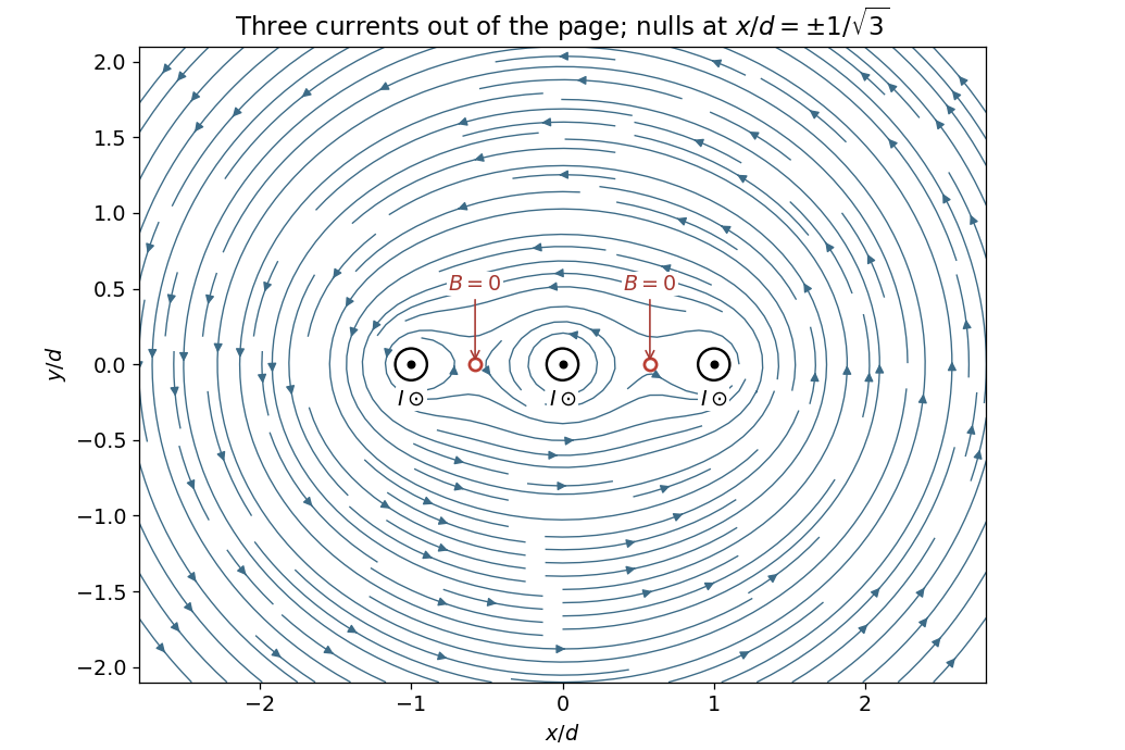
Magnetic field and two nulls for three equal parallel currents
. Coordinates are measured from the middle wire in units of the neighbouring-wire spacing. All three currents point out of the page; the two field zeros are marked between the wires. Details.
For a displacement of the middle wire, the horizontal attractions towards the two fixed outer wires cancel. Each attraction has magnitude per unit length. Projecting them in the direction givesNeglecting dissipative effects and other transverse forces, this is simple harmonic motion. Release from rest at givesThe inverse-angular-frequency timescale is ; it differs from the oscillation period by . The assumed displacement plane matters: small displacements towards one outer wire along are unstable, rather than oscillatory.
This result concerns the specified magnetic motion with gravity absent from, or compensated in, the direction. The source diagram fixes coordinate directions, not their orientation relative to gravity. If is physically vertical with upward positive and the wire is unsupported, add to the force per unit length. The maximum restoring magnetic force is only , compared with weight ; that different setup would fall and could not oscillate about the original plane.
In Fraunhofer diffraction, the source and observation geometry make the incident and outgoing wavefronts effectively planar across the aperture. For direct propagation over distance , the quadratic variation in propagation phase across a slit of width must be negligible, approximately . The far-field angular amplitude is then the Fourier transform of the aperture's complex illumination. A converging lens also produces this angular distribution in its rear focal plane for collimated illumination, without requiring a physically enormous observation distance. The approximation concerns the aperture-dependent phase, not the absence of diffraction.
Let the slit run over and let its coherent illumination have constant complex amplitude . In a direction making angle to the normal, the relative propagation phase from position is , with . Summing the secondary amplitudes givesThe intensity is proportional to the squared modulus, hence within the usual scalar Fraunhofer diffraction approximationThe central value is defined by the continuous limit . The nonzero minima satisfy for integer . This expression neglects the slowly varying obliquity factor and uses a uniform slit; it describes the narrow-angle diffraction pattern for .
The Rayleigh criterion declares two equal incoherent point images just resolved when the central maximum of one lies at the first minimum of the other's point spread function. For a single rectangular slit, the first minimum occurs at . ThusThis is a resolution in the direction across the slit width, and the last approximation requires . The central maximum's full width between its two first minima is approximately ; it is not the Rayleigh criterion's separation. Two coherent sources can interfere with one another, so a resolution statement for them also needs their relative phase.
A feature of transverse size at height subtendsChoose a representative visible wavelength . For an unobstructed circular mirror, the first Airy disk minimum gives , soUsing the single-slit scaling alone would give ; it gives the same metre-scale estimate but omits the circular-aperture factor. Choosing visible wavelengths between and changes the circular-aperture estimate to roughly –. These are diffraction-only estimates, not a claim that resolving one stroke guarantees reading arbitrary text with limited contrast or noise.
At focal length , the stroke maps to a focal-plane width . A practical estimate with two detector samples across that stroke isThe required sensor extent in that direction is . One pixel per stroke would give about pixels across, but cannot reliably encode a stroke's position and contrast as the image moves relative to the pixel grid.
For a precise interpretation of “fully resolve” as sampling the entire diffraction-limited incoherent image, use the optical intensity-transfer cutoff . The Nyquist–Shannon sampling theorem requires . With the circular mirror chosen in 10d,This stricter value retains the full circular-aperture spatial bandwidth; the and estimates use two samples per specified feature instead. An engineering design would provide further sampling and contrast margin. The distinction states the sampling convention rather than treating the order-of-magnitude estimates as contradictory.
For a long air-cored solenoid, Ampère's law applied to a rectangular loop running inside and outside the winding gives , with the external magnetic field negligible away from the ends. Hence along the winding axis, where . Each turn links magnetic flux with , so the total magnetic flux linkage is . It follows thatHere , and , so andThe value uses the stated long-solenoid approximation and ignores end corrections and winding resistance.
The original diagram places in parallel with the inductor; connects their common node to the source only when the switch is in position 2. Let be their shared voltage and the downward inductor electric current. Since and a finite voltage cannot change it instantaneously, the inductor initially behaves as an open branch. ThusAt long times, an ideal inductor carrying constant electric current has , shorting . Therefore and .
For the full transient, Kirchhoff's current law gives with . Equivalently, the source seen by the inductor has the Thévenin equivalentSolving givesThe relevant resistance is the parallel combination with the ideal voltage source suppressed, not and not alone.
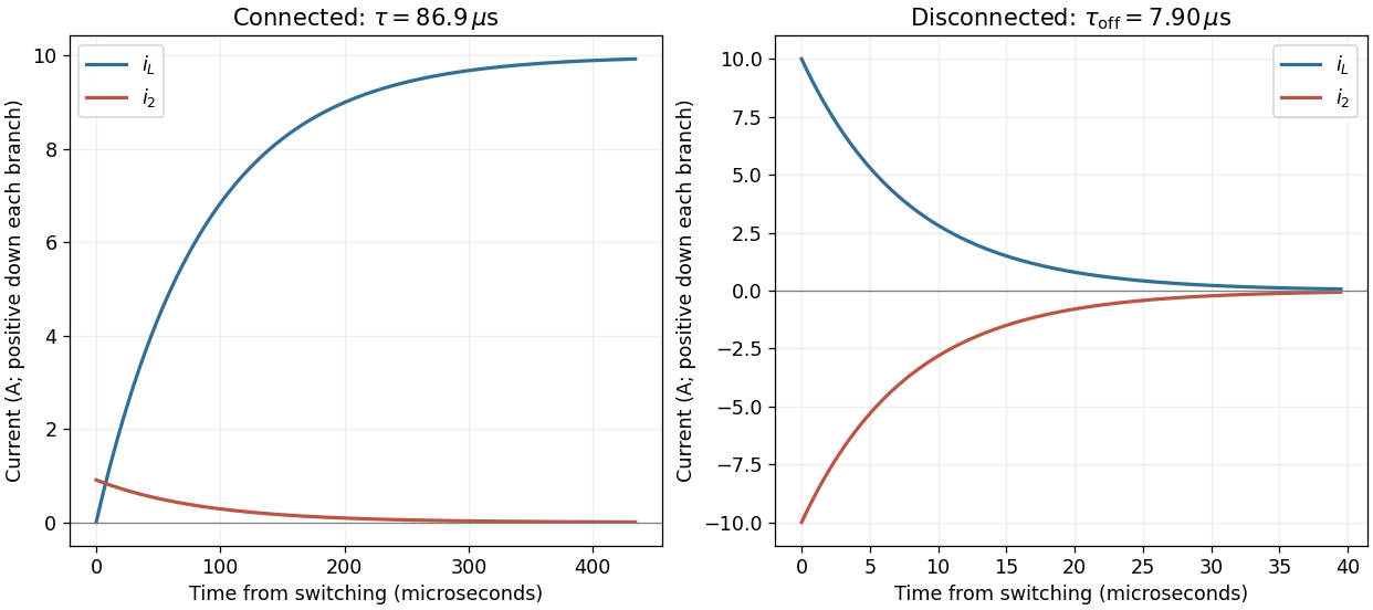
Current redistribution when the solenoid is connected and disconnected
. The two panels use their own time origins. On connection the inductor current grows while the parallel-resistor current decays. On disconnection both branches carry equal and opposite currents as stored magnetic energy dissipates. Details.
During switch-on, the Joule heating in has instantaneous power . Integrating the finite transient givesAlthough the source continues supplying power to indefinitely, is eventually shorted and its heat integral converges. It would be incorrect to identify this heat with the final stored magnetic energy, because the source and also participate during switch-on.
Opening the switch removes the source and but leaves a closed path through the inductor and . Set the new time origin at switch-off. Inductor current continuity gives . Since the two parallel branches are now isolated, Kirchhoff's current law gives , and . ThusAll the initially stored magnetic energy is ultimately converted to Joule heating in :Direct integration of gives the same result. The initial shared voltage is ; its reversal drives the return current. The ideal circuit permits this transient voltage; real switching would also be limited by stray capacitance, breakdown and other parasitic effects.
Articles by others on the same topic
There are currently no matching articles.