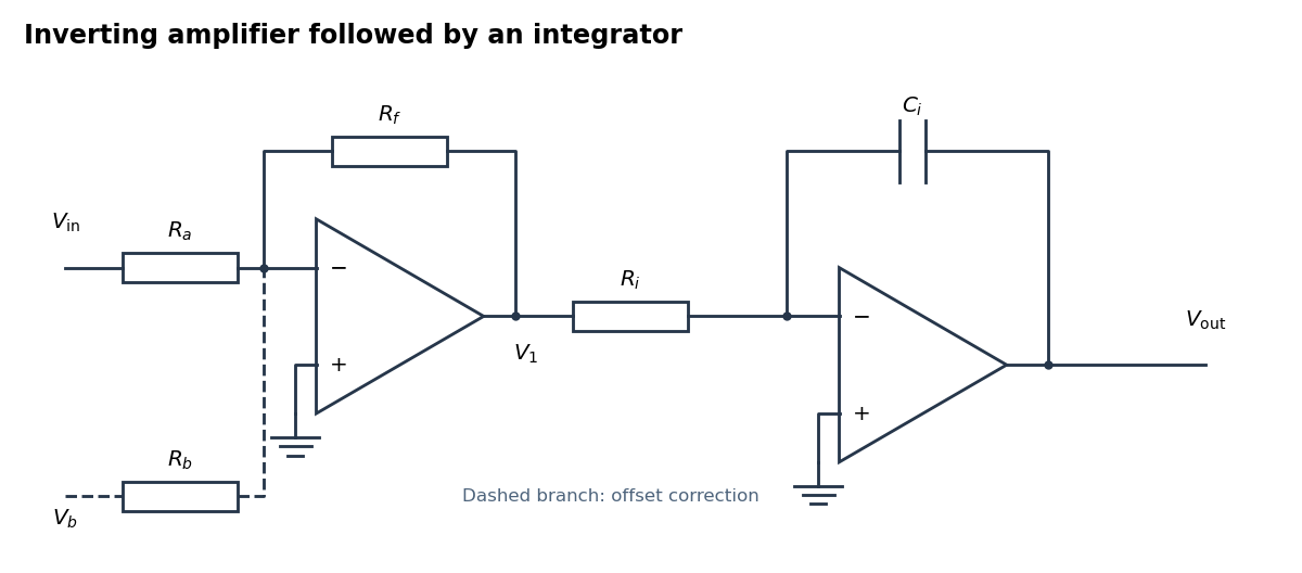
An inverting amplifier followed by an integrator, with an optional offset-correction branch
. Details. 
Use the following arrangement: an inverting operational amplifier with input resistor and feedback resistor , followed by an op amp integrator with input resistor and feedback capacitor . Ground both non-inverting inputs. Each ideal operational amplifier has infinite input impedance, so its inputs draw no electric current; negative feedback makes the inverting input a virtual ground.
Kirchhoff's current law at the first summing junction gives . At the second summing junction it gives . Consequently the two inversions cancel:The initial output voltage records the initial capacitor charge. A reset switch across sets it to zero. The formula holds while both stages remain within their supply rails; a persistent input voltage otherwise produces amplifier saturation.
Articles by others on the same topic
There are currently no matching articles.