The cover dates this ordinary sitting to 8 June 2021; the public bundle's filename does not identify the sitting year. Unlettered, separately marked answer blocks below are labelled a, b, and so on for navigation.
Write . The separation of the two point charges is , so Coulomb's law gives the horizontal repulsive force . Resolving the rod's tension vertically and horizontally gives and . HenceThe left side increases from zero to infinity for , so this determines a unique outward equilibrium. For a small angle, . With , direct numerical solution gives
A large electrical conductor between the point charges provides electrostatic shielding: one must not retain their original mutual Coulomb force through an ideal infinite plate. In the usual broad-plate approximation, let denote the unperturbed surface charge density on each face. The electrostatic boundary condition gives an outward electric field . Neglecting local electrostatic induction, the rod's tension then satisfies , givingThere are two physical qualifications. First, if means the total charge per projected plate area, shared equally between the two faces, then and the same approximation gives . The factor of two is a convention about the specified surface charge density, not a different Gauss's law.
Second, a point charge near an electrical conductor makes its surface charge density nonuniform. For an infinite plane with prescribed background electric field , the method of images adds an attractive force , where . The more accurate equilibrium equation isIts larger, stable root is approximately for the per-face convention, or for the total-area convention. This ideal-plane refinement is not an exact answer for an unspecified finite plate: its dimensions and the meaning of the quoted surface charge density would be needed. In particular, adding a uniform-sheet electric field to the original mutual repulsion would describe a different, nonshielding model.
At direct current an ideal capacitor is an open circuit. A finite measured electrical resistance therefore requires the resistor and capacitor to form a parallel circuit, with . Use phasors proportional to . The electrical admittance and complex impedance areInterpreting the stated AC value as the measured impedance magnitude, and give . ThusThe electric current leads the applied voltage by . Strictly, AC “resistance” is ambiguous: if it means , the same parallel circuit instead gives , , and . A measurement of selects the boxed interpretation.
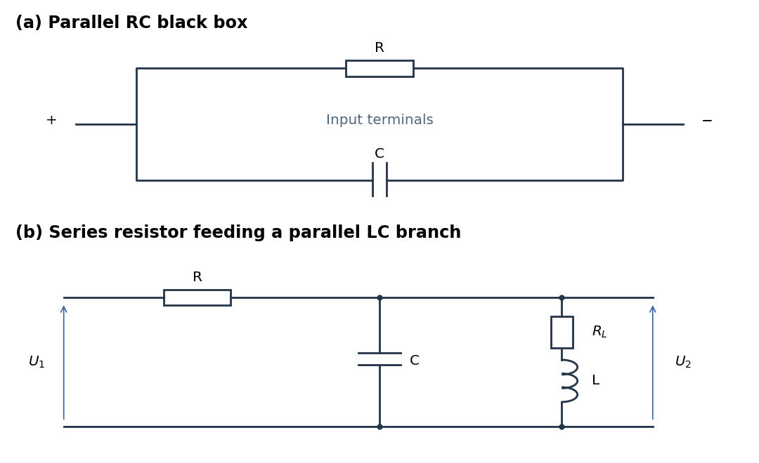
Parallel RC network and resonant voltage divider
. Details. 
A suitable electrical circuit has in series with the input and a shunt branch consisting of in parallel with the lossy inductor ; take the output voltage across that shunt branch. This is the middle arrangement in the circuit figure. In terms of its complex impedance,At direct current the capacitor is an open circuit and the inductor contributes only , so . ThereforeWhen is neglected, . At the antiresonance its electrical admittance vanishes, so reaches its maximum value of one. ConsequentlyThis value uses precisely the requested lossless approximation; keeping changes both the peak position and its height. A transfer function peak and one DC measurement do not uniquely identify every possible two-port network, but the displayed arrangement meets both observations to the stipulated approximation. Also, the angle brackets in the source must denote AC wave amplitudes or root mean square values: the literal time averages of sinusoidal voltages are zero, whose ratio would be undefined.
In vacuum, Maxwell's equations in differential form areHere is charge density, is electric current density, is electric field, and is magnetic flux density. In a source-free region, taking the curl of the third equation and using gives the wave equationThe same argument gives the wave equation for . A concrete family satisfying all four Maxwell's equations isThe function may be any twice differentiable profile. These are transverse travelling waves; reverse the magnetic field direction for propagation in the opposite direction. Because the source-free Maxwell's equations are homogeneous linear differential equations, any finite linear combination of such paired electric fields and magnetic fields is again a solution. Infinite superpositions also work whenever the required derivatives converge. A solution of the component wave equations alone must still satisfy the divergence and mutual-curl constraints.
For a plane electromagnetic wave with linear polarization, write and . The Poynting vector is instantaneous energy flux:The light intensity is its cycle average, not its peak:An incident electromagnetic wave transports longitudinal momentum per energy . Perfect reflection back along the incident direction reverses that momentum, transferring to the mirror. Dividing by illuminated area and time gives the mean radiation pressureHere denotes the incident travelling wave. The average net Poynting vector of the incident-plus-reflected standing wave is zero, although its radiation pressure is nonzero.
Use positive real object and image distances for a thin lens. The required absolute magnification is , and the specified LCD-to-screen separation gives , not . Since ,The thin lens equation yieldsPlace the projection lens beyond the LCD towards the screen. Its real image is inverted; the signed magnification is .
The condenser lens should image the point source onto the small projection lens. Then every illuminated LCD point directs its central light ray into the projection lens, rather than wasting light elsewhere. In the paraxial idealization this gives approximately uniform useful illumination.
Put the LCD at , the source at , the projection lens at , and the condenser lens at . The cone from the condenser lens's rim, of radius , to the projection lens has radiusat the LCD. Maximum approximately uniform illumination without unnecessary overfilling makes this equal the half-diagonal . Thus : place the condenser lens before the LCD, or after the source. Its object and image distances are and , soThe illuminated disk just contains the rectangular LCD. Exact spatially uniform irradiance is not guaranteed by a single spherical lens and a point source; the result uses paraxial geometrical optics, negligible optical aberration, and an approximately uniform incident cone.
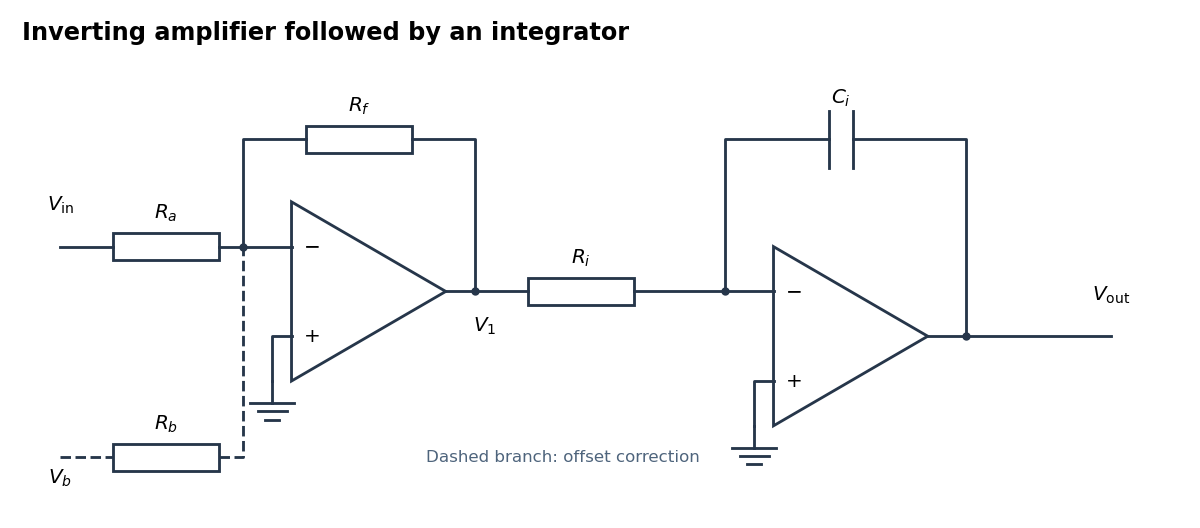
An inverting amplifier followed by an integrator, with an optional offset-correction branch
. Details. 
Use the following arrangement: an inverting operational amplifier with input resistor and feedback resistor , followed by an op amp integrator with input resistor and feedback capacitor . Ground both non-inverting inputs. Each ideal operational amplifier has infinite input impedance, so its inputs draw no electric current; negative feedback makes the inverting input a virtual ground.
Kirchhoff's current law at the first summing junction gives . At the second summing junction it gives . Consequently the two inversions cancel:The initial output voltage records the initial capacitor charge. A reset switch across sets it to zero. The formula holds while both stages remain within their supply rails; a persistent input voltage otherwise produces amplifier saturation.
Write , with constant unwanted offset . Add an adjustable reference voltage through another resistor to the first inverting summing junction, as the dashed branch in the circuit figure shows. Kirchhoff's current law now givesChoose the reference polarity and magnitude so thatA potentiometer between positive and negative reference supplies permits either sign. The first stage then has zero output voltage when , and the op amp integrator integrates only :Merely placing a large resistor across the integrating capacitor limits drift but also changes the transfer function; cancellation at the summing junction preserves ideal integration of the desired signal.
Neglect the entrance and exit capacitor fringing fields and use the coaxial electric field between the cylindrical plates. Let , with . The radial electric field isFor an electron, of electric charge , to follow the circular path , its inward centripetal force must be . ThereforeThe inner plate must be at higher electric potential: the electric field points outward and the electron's electric force inward. The electric force is perpendicular to the velocity, so no work is done and the speed remains . The required voltage is independent of the opening angle , which only sets the transit time . For a narrow gap, . This is a nonrelativistic, negligible-capacitor fringing field answer; finite open cylindrical sections do not have an exactly radial electric field at their ends.
For a uniformly illuminated single slit of width , summing the wave amplitudes across the slit gives the Fraunhofer diffraction profileThe first minimum occurs at . The Rayleigh criterion places one source's central maximum at the other source's first minimum; hence the slit gives . A circular aperture instead produces an Airy disk, whose first minimum is at . For the camera's circular lens,The factor belongs to circular-aperture diffraction, rather than the single-slit profile.
The Rayleigh criterion gives a separation in the sensor plane , using the image distance. Counting one square pixel per such spatial resolution element givesThis is an estimate of the number of optically distinguishable elements. To sample all the spatial information, specify a signal sampling criterion as well. For incoherent imaging through an ideal circular aperture, the optical transfer function has cutoff spatial frequency . The Nyquist–Shannon sampling theorem requires a pixel pitchA common intermediate rule, two pixels per Rayleigh separation, gives about million pixels; it is a heuristic and does not quite sample the full ideal optical transfer function bandwidth. Thus about million is the elementary spatial resolution element count, while million is the ideal monochrome Nyquist–Shannon sampling theorem answer to “full use.” Color-filter layout and finite pixel area would impose further practical conditions.
Take the grounded plane as . The method of images replaces it, in , by an image charge at and an image charge at . These make the electric potential zero on the plane; the uniqueness theorem for the electrostatic potential establishes the solution in the physical half-space.
At , both real point charges contribute upward electric fields, each of magnitude . The nearer image charge contributes downward and the farther one upward. HenceThis is upward for ; retaining signed automatically handles the opposite sign. No self-electric field is involved because the evaluation point is distinct from every point charge.
For image charges in a sixty-degree conducting wedge, use polar coordinates in a cross-section normal to the planes' intersection, putting the physical wedge at and the real point charge at . Repeated reflection in the two grounded faces produces five image charges, all at radius and the same coordinate along the intersection:Equivalently, the positive copies are at and the negative copies at , for . Only the original point charge lies inside the physical wedge.
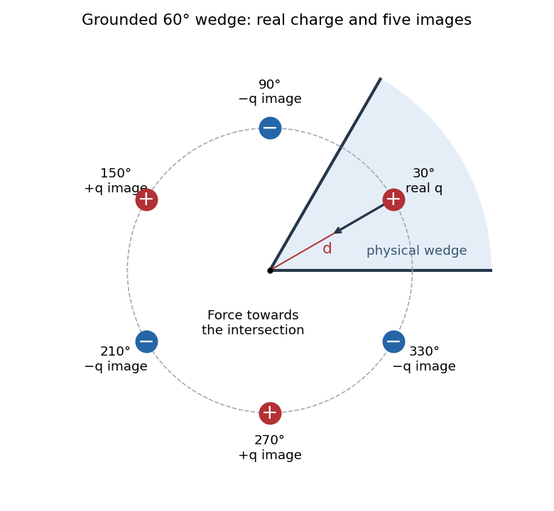
Five image charges outside the physical sixty-degree conducting wedge
. Details. 
For any observation point on either face, reflection pairs every positive point charge with an equidistant negative one. Their Coulomb potentials cancel, so both grounded faces have zero electric potential. The electric potential also tends to zero at infinity. The uniqueness theorem for the electrostatic potential then identifies this method of images construction with the physical solution.
Let point from the intersection to the real point charge. Reflection symmetry cancels the component of electrostatic force perpendicular to the wedge bisector. An image charge at angular separation from the real point charge gives radial forceThe two adjacent negative image charges have , distance , and combined radial force . The two positive image charges have , distance , and combined radial force . The opposite negative image charge is at distance and contributes . ThusThe electrostatic force is towards the intersection, independently of the sign of . One sums the five image charge electric fields and multiplies by ; the factor used in induced-charge electrostatic energy must not be inserted into this direct force calculation.
Let each slit alone give local light intensity , and assume equal coherent illumination. In Fraunhofer diffraction, the two wave amplitudes differ in wave phase by . Adding the wave amplitudes before squaring givesFor a flat screen, . In the paraxial region , the double-slit interference profile is thereforeThe given justifies the far-field expansion. Slit widths have been neglected; a finite width multiplies this profile by the single-slit diffraction envelope. At large angles the one-slit light intensity and geometric spreading must also be retained, rather than treating as constant.
The screen now lies in the back focal plane of the lens. In paraxial geometrical optics, a light ray arriving at the lens at height and angle leaves at angle , and reaches the screen atThus all light rays with the same incident direction reach the same screen coordinate, independently of their height at the lens. The Fraunhofer diffraction pattern is an angular pattern mapped to :Here is the one-slit light intensity after focusing. Its absolute value depends on collected light and the lens aperture, which are unspecified; it need not equal the no-lens value . Propagation from the slits to the lens introduces a common angular wave phase, so it does not alter the relative wave phase responsible for these fringes, provided the aperture passes the required light.
The slide adds optical path length to the covered beam. Put the covered slit at transverse coordinate . For positive screen coordinate its geometrical path is shorter by approximately , so the total covered-minus-uncovered optical path difference isThe zero-order fringe follows equal total optical path lengths, . HenceThe covered beam needs a shorter geometric path to compensate its extra optical path length. This is the paraxial estimate; exact point-to-point distances give . “Central” here follows the zero-order fringe continuously as the slide is introduced. At one fixed wavelength, the final monochromatic wave interference pattern is periodic, so intensity alone identifies a fringe position only modulo the fringe spacing. Slide reflections and absorption have been neglected.
The two optical frequencies have no persistent mutual optical coherence over the detector's averaging time, so their light intensities add. Assuming equal strengths and using , let be the one-slit light intensity at either wavelength. ThenThe identity rewrites this asThe slowly varying interferometric visibility is approximately . Its first zero occurs atThe rapid fringes have effective wavelength , so the first contrast minimum is at order . Thus the conventional estimate is about 13 fringes on each side, before their first washout, plus the central maximum. “Clearly” is not a specified visibility threshold: the last of those fringes already has low contrast.
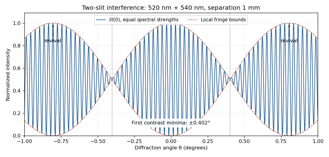
Two-wavelength interference, its first visibility minima, and contrast revival over minus one to plus one degree
. Details. 
The fringes do not disappear permanently beyond that point. Their contrast revives; the first exact common maximum satisfies , at . This is a concrete counterexample to interpreting 13 as a global bound on visible fringes. Unequal spectral strengths would leave nonzero residual contrast at the nominal washout; the plotted equal-strength case is the natural interpretation in the absence of specified strengths.
With phasors proportional to , the resistor, inductor, and capacitor have complex impedances , , and . In a series circuit they carry the same electric current, so their voltage drops add:The real part describes Joule heating; the imaginary part changes sign between capacitive and inductive response, passing through zero at .
The voltage divider relation for the capacitor output gives the transfer functionConsequently the relative wave amplitude isFor input , the output is , where the continuous phase shift isFor positive frequency and , this phase shift goes from towards , passing through at . A one-argument arctangent without a quadrant correction would wrongly predict a positive phase shift above . The capacitor follows a slowly varying input voltage, while its output falls as at high frequency.
At the inductive and capacitive electrical reactances cancel, so the complex impedance is and the electric current amplitude is . The capacitor voltage amplitude is . Thus the specified quality factor isA capacitor output exceeding the input voltage is consistent with a passive electrical circuit: the inductor and capacitor voltages largely cancel in their sum. The expression assumes positive ; the ideal undamped limit has no finite steady resonant response.
Put . Maximizing the output wave amplitude is equivalent to minimizingIts derivative is . An interior minimum at positive frequency therefore requires , and occurs atIndeed , and the peak value is . For , increases for and the largest output is the DC value . At equality the putative peak has reached zero frequency; there is no distinct nonzero-frequency resonance. This threshold concerns capacitor voltage peaking: the series RLC circuit's electric current still has its maximum at for every positive .
Faraday's law of induction states that the induced electromotive force around an oriented closed circuit equals the negative rate of change of linked magnetic flux. For a stationary circuit,Here is electric field, is magnetic flux density, and the oriented surface has the circuit as its boundary. For identical series turns, replace by the total flux linkage . Lenz's law supplies the sign: an induced electric current opposes the change of linked magnetic flux, in agreement with conservation of energy.
If the wire moves with local velocity , the more general electromotive force includes the magnetic Lorentz force per unit electric charge:The boundary and surface orientations in both expressions are related by the right-hand rule.
In the long-solenoid approximation, the internal magnetic flux density is uniform, , and the external magnetic field is negligible. This follows from the magnetostatic Ampère law applied to a rectangular loop running inside and outside the solenoid. Its number of turns is and its cross-sectional area is . Each turn links magnetic flux . Therefore the flux linkage isUsing the definition of self-inductance, , givesThis neglects end leakage and winding thickness and uses vacuum permeability for the air core.
For the imposed electric current , Faraday's law gives the self-induced electromotive forceThe externally applied terminal voltage, with the passive sign convention, has the opposite sign:Thus the terminal voltage leads the electric current by . The instantaneous input power isAn ideal inductor alternately stores magnetic energy and returns it to the source. Real winding electrical resistance would add mean Joule heating ; the ideal zero result assumes that loss is neglected.
The single secondary turn links the primary magnetic flux , so its mutual inductance with the primary isChoose positive winding directions so that positive secondary electric current would reinforce the primary magnetic flux. Faraday's law and Kirchhoff's voltage law then giveAfter the transient proportional to has decayed, put . The steady electric current isIts wave amplitude is and it lags the induced electromotive force by . Relative to the primary , its phase shift is , modulo . Reversing the chosen secondary winding direction adds to this signed phase shift and leaves all power predictions unchanged.
The lamp's mean Joule heating isFor the response is nearly in phase with the induced electromotive force; for the secondary electric current nearly opposes the primary electric current in the stated winding convention.
The positive lamp power comes from extra work by the primary current source. The secondary electric current creates a changing magnetic flux through the primary, so maintaining the same prescribed primary electric current requires an additional terminal voltage. With the preceding winding convention,Using phasors, , hence the primary sees the complex impedanceIt follows directly thatThis is the reflected impedance of the secondary load. The self-inductance and mutual inductance terms exchange stored magnetic energy, while the lamp dissipates it. Multiplying the two coupled equations from Kirchhoff's voltage law by their respective electric currents also gives the instantaneous conservation of energy identityThe derivative averages to zero in periodic steady state. A fixed primary current source supplies the required extra voltage; a fixed voltage source would generally change its primary electric current when the lamp is connected.
Articles by others on the same topic
There are currently no matching articles.