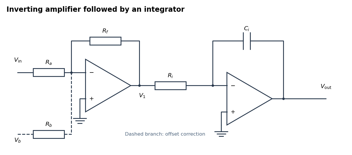
An inverting amplifier followed by an integrator, with an optional offset-correction branch
. Details. 
Use the following arrangement: an inverting operational amplifier with input resistor and feedback resistor , followed by an op amp integrator with input resistor and feedback capacitor . Ground both non-inverting inputs. Each ideal operational amplifier has infinite input impedance, so its inputs draw no electric current; negative feedback makes the inverting input a virtual ground.
Kirchhoff's current law at the first summing junction gives . At the second summing junction it gives . Consequently the two inversions cancel:The initial output voltage records the initial capacitor charge. A reset switch across sets it to zero. The formula holds while both stages remain within their supply rails; a persistent input voltage otherwise produces amplifier saturation.
Write , with constant unwanted offset . Add an adjustable reference voltage through another resistor to the first inverting summing junction, as the dashed branch in the circuit figure shows. Kirchhoff's current law now givesChoose the reference polarity and magnitude so thatA potentiometer between positive and negative reference supplies permits either sign. The first stage then has zero output voltage when , and the op amp integrator integrates only :Merely placing a large resistor across the integrating capacitor limits drift but also changes the transfer function; cancellation at the summing junction preserves ideal integration of the desired signal.
Articles by others on the same topic
There are currently no matching articles.