A rectifier converts an alternating input into a unidirectional output. Diode orientation selects which direction of electric current is transmitted.[ref]
An electrical circuit that uses diodes and capacitors to produce an output electric potential difference larger in magnitude than the input peak. The attainable output depends on the circuit arrangement, electric current drawn by the load, capacitance and input frequency; an ideal unloaded result does not specify the output under load.
For an original ideal example, let an ideal voltage source supply the sinusoid , with and angular frequency . Connect its positive reference terminal to the diode anode, the diode cathode to the upper terminal of a load resistor with electrical resistance , and the lower terminal to the source return. Let be the upper-minus-lower load electric potential difference, and the downward load electric current. Assume the ideal diode model, zero source electrical resistance, and no filter capacitor, inductor or switching delay.
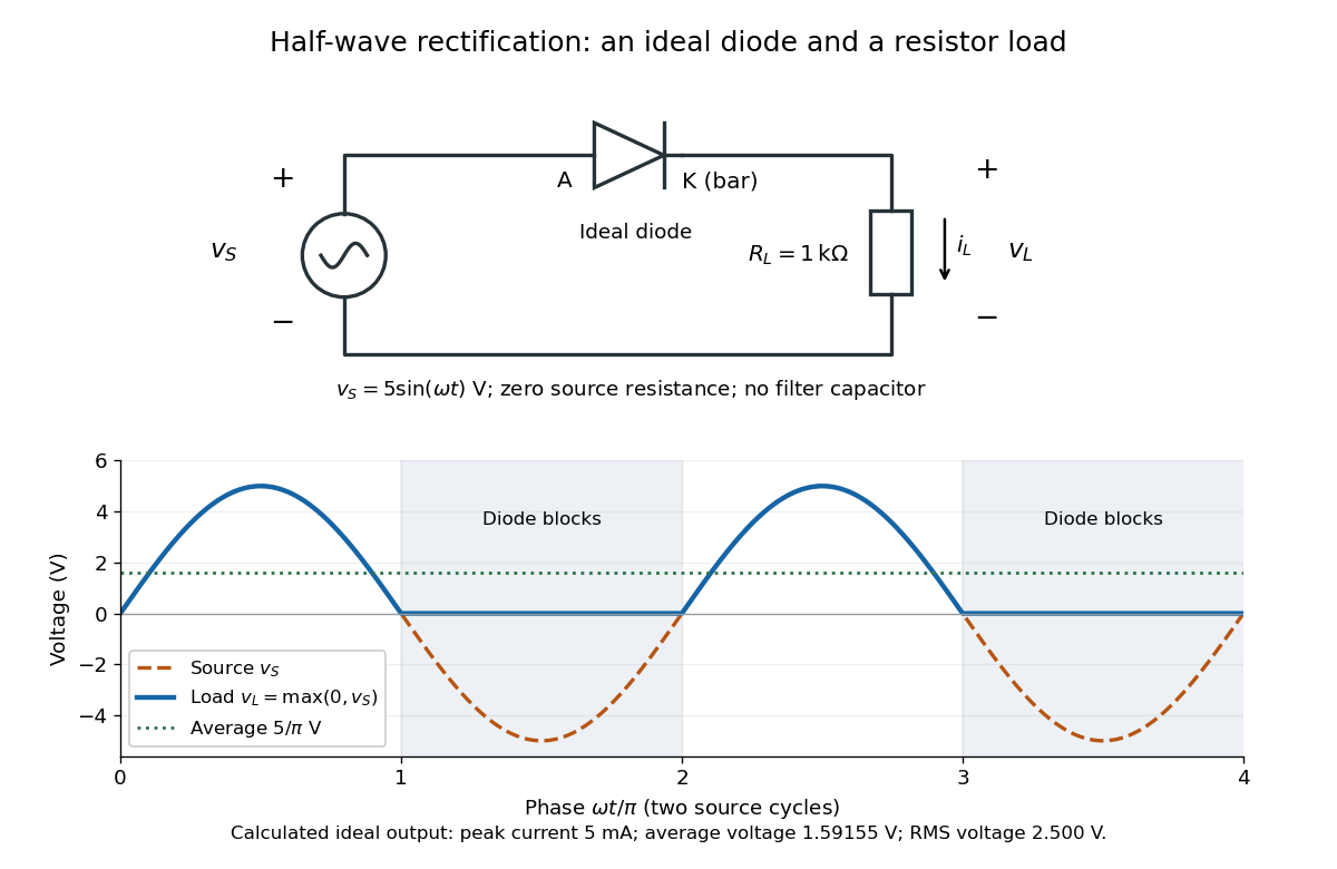
An ideal half-wave rectifier selects the positive half-cycle
. Original schematic and calculated load electric potential difference for and . The diode cathode is the bar at ; positive load electric current flows downward through the resistor. Dashed orange: source sinusoid. Blue: load output, zero during the negative half-cycle. Green: its cycle-average electric potential difference . No smoothing capacitor is present; these are ideal model predictions. Details.The Kirchhoff cycle law gives , and Ohm's law gives . If , the blocking assumption would give , contradicting the ideal diode model, so the diode conducts with . If , conduction would give , also forbidden, so the diode blocks. At the crossings both values vanish. ThusThe peak load electric current is . The output is unidirectional but still varies in time, reaching zero throughout every negative half-cycle. Over a period of a function , write the wave phase as . Its average value of a function and root mean square follow from two integrals:Consequently the average load power is , not . The ideal diode has zero loss; the resistor converts supplied energy into Joule heating. The same switching argument predicts when the diode is reversed. Directional selection changes the waveform and its average value of a function; it does not by itself produce a constant output.