The motivating observation is that inserting an insulating material between fixed capacitor plates increases its capacitance. [ref]
https://www.feynmanlectures.caltech.edu/II_10.html#Ch10-S1. Feynman, Leighton and Sands, II.10–1, opening paragraphs: observed increase in capacitance with an inserted insulator
. To investigate this response, use two flat parallel metal electrodes with measured overlapping area and separation , a uniform specimen filling the gap, and an instrument that measures electrical impedance. Record the capacitance with and without the specimen at the same small applied electric potential difference, frequency and temperature, after capacitance measurement calibration. An increase in corrected capacitance indicates a larger permittivity, provided the geometry is unchanged. A guard electrode reduces the contribution of the fringing field of a capacitor. [ref].For negligible dielectric loss in the parallel-plate capacitor approximation,An air reference approximates ; it is not an exact vacuum reference. For the following synthetic example, stipulate , and the rounded vacuum permittivity . Then in this model, and relative permittivity four gives . A residual parallel capacitance of would make an uncorrected sample/reference ratio , rather than four. This additive error does not cancel in a ratio.
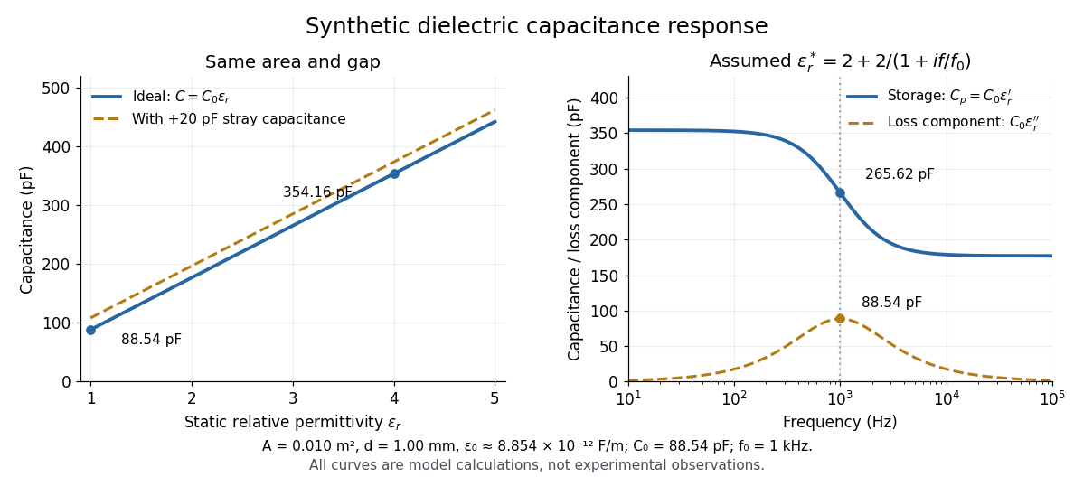

At nonzero frequency , measure both magnitude and phase of the electric current relative to the applied electric potential difference. Define , where is electrical impedance. For the stated complex permittivity convention, the ideal uniform specimen givesThus a parallel capacitor and electrical conductance describe the readout at that frequency; a single scalar capacitance cannot describe both components. The diagram's assumed dielectric relaxation gives and at . These are model predictions, not observations.
Repeat the reference measurement after removing the specimen and vary the small applied electric potential difference to test drift and linearity. Record specimen thickness, electrode area, contact conditions, frequency and temperature. Air gaps act as additional layers in series and can lower inferred relative permittivity; roughness, uncertain thickness and the fringing field of a capacitor limit the geometric formula. At sufficiently high frequency, the fixture itself changes the electromagnetic field, so low-frequency guarding and a lumped capacitor model require reassessment. [ref].
Articles by others on the same topic
There are currently no matching articles.