A NACA four-digit airfoil encodes three quantities: maximum airfoil camber in hundredths of the airfoil chord, its position in tenths of the airfoil chord, and nominal maximum airfoil thickness-to-chord ratio in hundredths. Thus NACA 2412 means , and ; NACA 0012 has zero airfoil camber and the same nominal thickness ratio.[ref]
With , the airfoil mean camber line isFor a symmetric airfoil, take directly; do not divide by the zero position parameter. The half-thickness follows the polynomial in trailing edge. If , the upper/lower coordinates areThickness is placed along a normal vector to the mean line, rather than simply added vertically.[ref]
For an original NACA 2412 calculation at , the mean-line slope is zero, and the standard finite-edge polynomial gives . Hence the surface points are approximately and in chord-normalized coordinates. A 12-percent designation does not mean the section is 12 percent thick at every chordwise position.
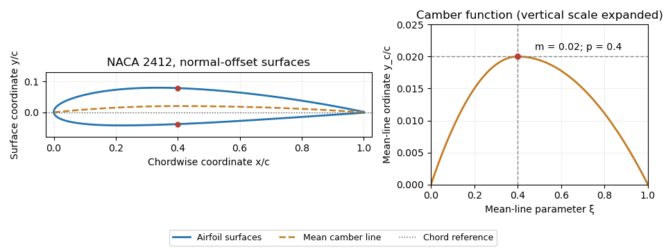
NACA 2412 mean camber line and surfaces constructed by normal offsets. Original evaluation of the stated four-digit equations.
Details. 
The trailing-edge convention must also be specified. The usual coefficient leaves a small finite thickness; the modified closes the endpoint. With a sloping mean line, the upper and lower endpoint coordinates can differ in both components, so directional measurement of trailing-edge thickness must state which separation it reports. These constructions define geometry, not a universal aerodynamic performance curve.
NACA 4412 is a NACA four-digit airfoil with maximum airfoil camber of the airfoil chord, its maximum at chord, and nominal maximum airfoil thickness-to-chord ratio . Thus the first two digits specify a mean-line shape, while the last two specify a thickness-envelope parameter. The designation is geometric rather than a universal measured lift coefficient.[ref]
For an original section, the maximum mean-line displacement is 20 mm at a station 200 mm aft of the mean-line origin. The nominal twelve-percent thickness is 60 mm. That thickness does not occur at every station and is not the same quantity as maximum camber.
A calculation away from the maximum-camber station makes the airfoil thickness convention visible. At the mean-line parameter , the standard construction givesUsing the finite-trailing-edge thickness polynomial and normal offsets, the upper and lower points areTheir different horizontal coordinates are part of the construction. Adding and subtracting the same half-thickness vertically would create a different profile at this station.
Compared with NACA 2412, the mean-line amplitude is doubled while and the prescribed thickness envelope are unchanged. Thin airfoil theory therefore doubles the camber contribution to its modeled zero-lift angle of attack; direct evaluation gives about for this ideal mean line. That number follows from the ideal model and is not a wind-tunnel measurement. It does not establish a universal aerodynamic stall angle or drag curve.
The physical motivation for a related family was to vary thickness and mean-line form systematically, then measure the resulting aerodynamic behavior under controlled conditions. The original NACA report describes such a comparison in a variable-density wind tunnel at large Reynolds number.[ref]
The Characteristics of 78 Related Airfoil Sections from Tests in the Variable-Density Wind Tunnel by Eastman N. Jacobs and others. Summary, systematic variation of thickness and mean-line form
A performance statement about NACA 4412 must still identify flow conditions, surface condition and the measured quantity.NACA 0012 is a NACA four-digit airfoil with zero specified airfoil camber and nominal maximum airfoil thickness-to-chord ratio . Its upper and lower thickness envelopes are reflected across the airfoil chord, making it a symmetric airfoil. The designation describes section geometry; it is not a measured lift or drag specification.[ref]
To construct it, set the airfoil mean camber line to zero directly and use the standard thickness envelope in trailing edge with . No mean-line location parameter is needed. For the finite-edge convention, the normalized half-thickness at is . An original section with therefore has surface heights at that station and full local thickness . The nominal maximum thickness is about ; twelve percent is not the thickness at every station.
Its nose-radius formula is . The same chord gives . The finite-edge polynomial also leaves a small nonzero rear gap; closing that endpoint changes the coordinate specification. These are consequences of the stated construction, not independent manufacturing measurements.
A useful physical test records pressure and section lift while varying angle of attack at controlled Reynolds number. Thin airfoil theory predicts a zero zero-lift angle of attack for the symmetric ideal model, but it does not supply a universal aerodynamic stall angle. The original NACA experimental programme systematically compared related shapes in a variable-density wind tunnel, providing a reason to identify both the section and the flow conditions when citing results.[ref]
The Characteristics of 78 Related Airfoil Sections from Tests in the Variable-Density Wind Tunnel by Eastman N. Jacobs and others. Summary and profile-family investigation
NACA 2412 is a NACA four-digit airfoil with maximum airfoil camber two percent of the airfoil chord, located at forty percent chord, and nominal maximum airfoil thickness-to-chord ratio twelve percent. It combines a nonzero airfoil mean camber line with the same nominal thickness parameter as NACA 0012.[ref]
The construction is developed in NACA four-digit airfoil. A new calculation away from the maximum-camber station illustrates its normal offsets. At , the mean line gives and . The finite-edge thickness polynomial gives . With , the normalized surface coordinates areTheir midpoint is exactly the construction point before numerical rounding. Their horizontal coordinates differ because thickness is placed along the local normal vector. Simply adding and subtracting vertically would produce a different geometry at this sloping station.
For a chord, these paired points are separated by . This local normal separation is smaller than the nominal maximum thickness. Airfoil thickness convention explains why a projected or same-horizontal-station measurement must be distinguished from this paired normal distance.
The two-percent camber is not a two-degree incidence or a prescribed lift coefficient. Its aerodynamic effect depends on the mean-line slopes and the flow. A wind tunnel comparison with NACA 0012 can hold nominal thickness and Reynolds number fixed while observing the change due to airfoil camber. Such comparisons follow the systematic separation of thickness and mean-line form in the original NACA investigation.[ref]
The Characteristics of 78 Related Airfoil Sections from Tests in the Variable-Density Wind Tunnel by Eastman N. Jacobs and others. Summary and derivation of related airfoil sections
Articles by others on the same topic
There are currently no matching articles.