A two-dimensional electron gas is confined into discrete subbands perpendicular to an interface while retaining nearly free motion in its plane. It is not a literal zero-thickness electron sheet. In a GaAs/AlGaAs semiconductor heterostructure, the band offset and self-consistent band bending confine electrons on the GaAs side. Donors in AlGaAs can supply electrons while an undoped spacer separates them from the ionized dopants, reducing impurity scattering. This modulation-doping arrangement yields a high-mobility channel, with the lowest confinement subband occupied when the confinement spacing exceeds the Fermi and thermal scales. Gates tune the density or locally deplete the channel into constrictions. Low-temperature Hall and longitudinal measurements test the resulting sheet density and transport quality.
Use the magnitudes of the single-electron-band Drude Hall relation and longitudinal sheet resistivity:The given values are two-dimensional resistivities, so no sample thickness is inserted. ThusThe carrier sign follows from a specified Hall-voltage orientation; these calculations use positive magnitudes. A parallel conducting layer, several occupied subbands or a quantized Hall plateau would require a different interpretation of a single-field measurement.
For a parabolic two-dimensional electron gas with one valley and two spin states, the density of states per area is . Integrating from the subband edge to the zero-temperature Fermi energy gives , henceHere , and the energy is measured from the occupied subband bottom. Equivalently . ThereforeThe spin factor is already included in ; counting it again would halve the energy incorrectly.
This is transverse magnetic focusing. The depleted gates form reflecting boundaries and two constrictions. A narrow quantum point contact collimates carriers into cyclotron trajectories with cyclotron radius . When an integer number of semicircular skipping arcs links the two openings, the collector couples particularly strongly to the injector population. A floating voltage contact then changes its electrochemical potential to satisfy zero net current, producing a peak in the measured nonlocal voltage. Sweeping the field changes the arc diameter, moving the focused population into or away from the collector.
The connection condition is for integer , with the higher orders requiring specular reflections. The effect needs ballistic electron transport, sufficiently narrow openings and a smooth boundary. Electron phase coherence can add interference structure, but the basic geometrical focusing condition is semiclassical.[ref]
Coherent electron focusing with quantum point contacts in a two-dimensional electron gas by H. van Houten and others. Physical Review B 39 (1989), pp. 8556–8575, focusing geometry and peak structure
There is a polarity qualification in the printed geometry. The electron charge is negative: for a field out of the page, an electron launched upward through the left opening bends left, not toward the right opening. A direct left-opening-to-right-opening focusing path in the upper region therefore requires the field into the page; the printed outward field supports the reverse connection. Reversing conventional current reverses the occupation perturbation and voltage sign, but does not reverse the curvature of an individual electron. Thus the standard injector-to-collector explanation describes the focusing mechanism, while the asserted signed voltage increase requires a consistent field/lead convention. The calculated results below are peak-field magnitudes; taking outward field positive gives negative fields for direct left-to-right electron injection.
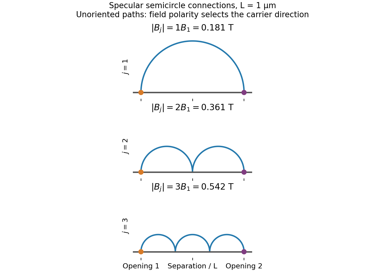
Original semicircular connections for three focusing orders; trajectories are shown without carrier-direction arrows
. Details. 
Substituting into givesUsing the density-derived Fermi wave vector gives the first three peak magnitudesThe equally spaced sequence follows from the number of reflected half-orbits, not from successive quantum Hall fillings. The field polarity selecting a given injector–collector orientation follows from the Lorentz force direction.
The transport mean free path is , while . Eliminating the scattering time gives . The usual ballistic focusing mobility criterion therefore givesA more geometrically faithful first-peak survival criterion uses the semicircular path length , giving . There is no sharp universal visibility threshold: clearly resolved peaks favour , small aperture broadening and specular reflection. The mobility inferred in part (ii) corresponds to , comfortably above both estimates. Higher-order peaks can still be reduced by boundary roughness even when bulk mobility is high.
Treat the top gate as a parallel-plate capacitor, neglecting fringing and assuming its voltage change couples to the 2DEG without a dominant trap or series-capacitance correction. Its capacitance per area and induced electron density areIn this top-gate density tuning, a positive gate change increases the electron density in this model, giving . Since ,The fields rise by a factor , not by the density ratio itself. Finite quantum capacitance is a small correction here: the one-subband value is much larger than the stated geometric capacitance per area.
The highest-field plateau is labelled , so it is the plateau in the filling factor, with the longitudinal resistivity returning to approximately zero after the transition near 10 T. The odd integer indicates a resolved spin branch at these fields; assuming a permanent twofold spin degeneracy for every orbital Landau level would misidentify the plotted sequence.
For a nominal exactly filled state at a chosen field , the density target is . Combining this with the same gate capacitor model gives the required gate-voltage change relative to the original ungated-density reference:Taking as the graph's onset-scale estimate gives andRelative to the positive 0.2 V setting in part (v), this is an additional change of approximately . An absolute laboratory gate voltage cannot be obtained without its initial offset or threshold; the calculated quantities are voltage changes.
There is a graphical/model qualification: a quantum Hall plateau occupies a finite field interval, and its onset is not an exact statement that at that edge. The plot identifies from about 10 T onward but does not specify a unique plateau-centre field or the gate setting at which the trace was recorded. The boxed formula gives the result for any selected target field. For comparison, the nominal exact-filling fields are 12.39 T at the original density and 18.34 T at the unchanged positive 0.2 V density. Thus the graph must not be combined silently with the latter density as if its onset uniquely fixed the same gate bias.
Articles by others on the same topic
There are currently no matching articles.