Birefringence means that two independent polarization eigenmodes have different refractive indices at the same frequency and propagation direction. The rotatory-power formula relevant here requires circular birefringence: the eigenmodes are opposite circular polarizations. General linear birefringence instead introduces phase retardation between linearly polarized components and need not rotate every incident linear polarization through one common angle.
Use the complex amplitude convention and transverse unit vectors . DefinePropagation through thickness adds phases , where is the vacuum wavelength. Recombining the two components givesThus the rotation and the specific rotatory power per unit length areThe units of are . The sign follows the specified circular basis and viewing convention. Equal attenuation of the two eigenmodes has been assumed; unequal attenuation also produces elliptical polarization.
Flint glass is approximately optically isotropic without an applied magnetic field. A longitudinal magnetic field changes the motion of its bound Electrons: the magnetic part of the Lorentz force acts with opposite sense on the two circularly rotating components of a driven electronic oscillation. Their optical response, and hence their refractive indices, split. Equivalently, the transverse permittivity tensor acquires a field-odd antisymmetric contribution whose eigenvectors are opposite circular polarizations.
The resulting circular birefringence gives Faraday rotation. For a weak longitudinal bias it is linear in the field:Here is the Verdet constant and the path length. The magnetic field breaks time-reversal symmetry, which is why this rotation is nonreciprocal. Reversing the bias reverses the rotation; reversing propagation while keeping the bias fixed does not undo it when physical polarization directions are compared in fixed laboratory axes. A transverse magnetic bias can have different, higher-order effects; the setup here is the longitudinal Faraday effect.
Choose the first polarizer's pass axis as and write the second as . The positive signed rotation takes toward by the short angle. Let be signed according to . The Jones matrices of ideal polarizers are their orthogonal projection matrices,Removing the unimportant common propagation phase, the lossless glass block has the rotation matrixThe elements act from right to left, soWith the common optical phase retained, multiply this by . Extra scalar attenuation would also multiply the result, but none is supplied. A single Jones vector does not represent unpolarized light; the device's Jones matrix is nevertheless well defined for each incident component and can be applied to their statistical mixture.
Let be the incident light intensity. The first ideal polarizer transmits and produces linear polarization along . Faraday rotation turns that direction through , and Malus's law at the second polarizer givesEquivalently, use the input coherency matrix and . This produces the same one-half factor required by unpolarized light.
Maxima satisfy , with . For and , the smallest field magnitude isIts direction is the axial direction that rotates the polarization passed by toward the pass axis of through the shorter . In the right-handed ray-basis convention where and the depicted second axis is , this is , along . Reversing that field at the same magnitude gives and zero transmission. A signed Verdet constant is meaningful only together with its rotation convention, so the polarization-alignment description fixes the physical direction without relying on ambiguous clockwise labels in a perspective diagram.
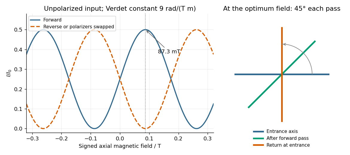
Original forward and reverse transmission curves and laboratory polarization directions at the optimum Faraday rotation
. Details. 
Keep the magnetic field fixed in the laboratory and exchange source and observer. The incident unpolarized light now meets first. In fixed transverse laboratory axes the backward glass map is still , not : this is optical nonreciprocity of the Faraday effect. The order of the two polarizers is reversed, soThe reverse light intensity is thereforeFor the optimal forward setting , it vanishes: the input selected by rotates to and is blocked by . At a general field, . The result assumes equal incident light intensities in the two experiments. Treating the glass as a reciprocal natural optical rotator would predict cancellation of its laboratory rotation on reversal and would give the wrong answer here.
Keep source, observer and magnetic field in their original places, but interchange the physical polarizers, including their pass-axis orientations. The forward order is then , glass, , so the new Jones matrix is again . ConsequentlyThis is the same intensity change as exchanging source and observer. At the field that maximizes the original forward transmission, the swapped arrangement blocks the beam. If both operations were performed together, the original order relative to propagation would be restored and so would the original transmission. The answer concerns exchanging the two differently oriented pass axes; simply relabelling two identical polarizers while leaving their axes fixed would not change the apparatus.
Articles by others on the same topic
There are currently no matching articles.