The real image is upside down. A converging optical lens produces negative transverse magnification on the screen: a point above the optical axis sends a central light ray through the optical lens centre to a point below the optical axis. The same happens in the horizontal direction. Viewed directly from behind, the screen therefore shows a picture rotated through relative to the scene.
The image is upright vertically when viewed down from behind, but left and right are interchanged. To track the image formation, let point forwards and upwards. Incoming light travels along . The flip plane mirror sends it along . Before this reflection, the optical lens has inverted the scene's top into the direction; the law of reflection maps that direction into on the horizontal screen. The screen's far edge is the top of the picture for someone looking down from behind. The horizontal inversion from the optical lens remains, since this plane mirror does not change the lateral coordinate.
The minimum is two additional plane mirrors, making three including the flip plane mirror. Their reflecting planes can meet at in the vertical section, as in a pentaprism. For example, in the section take the first added reflecting plane at to and the second at . The upward beam first travels diagonally forwards and upwards, then horizontally backwards towards an eye looking forwards. The two reflections together rotate directions through : the propagation direction becomes , while the screen's top direction becomes at the eye. Thus the picture remains upright vertically.
One additional plane mirror would also send into , but it would send the top direction into , making the image upside down. This proves minimality for ordinary plane mirrors. The three-reflection arrangement still reverses left and right; correcting that additionally requires a roof arrangement or another suitable image-erecting system. Vertical erection alone is what is asked here.
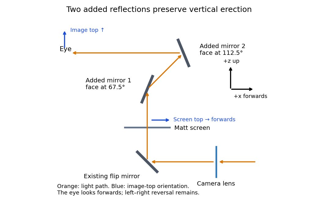
An original vertical-section ray construction with the minimum two added plane mirrors
. Details. 
Use a converging thin lens as a magnifying glass, with the screen at or just inside its front focal plane. It presents an upright virtual image at infinity or at the eye's near point, respectively. Let the near point distance be ; the conventional numerical assumption is , which is not specified in the paper.
Under the usual approximation that the eye is close to the eyepiece, interpreting as the focal length gives the familiar angular magnificationsThe first is for a relaxed eye with the screen at the front focal plane. For the second, the virtual image is at signed distance and the thin lens equation gives screen distance . Thus the often intended maximum requires a screen-to-eye distance of approximately , rather than exactly .
If instead fixes the physical screen-to-eye separation , an eye adjacent to the optical lens sees the angular magnificationThis is achieved by for relaxed viewing, or by for a virtual image at the near point. The latter follows from .
More generally, the source does not specify the eyepiece-to-eye distance either. If that distance is , then and a virtual image at the near point has transverse magnification . Its angular magnification relative to unaided viewing at isFor example, and give , with and . This is a concrete counterexample to a universal maximum of at fixed screen-to-eye separation. In ideal geometrical optics, allows arbitrarily large with an arbitrarily short focal length; practical aperture and optical aberrations constrain this. A unique numerical maximum therefore needs the conventional near-eye eyepiece geometry and near point assumption. The conventional answer is , with those assumptions stated explicitly.
Articles by others on the same topic
There are currently no matching articles.