Source paper: www.whatdotheyknow.com/request/physics_preliminary_past_papers/response/2680788/attach/3/2018%202021%20Physics%20prelims.zip?cookie_passthrough=1 (archive member
2020/L/a10288w1.pdf; the cover dates this sitting to 7 September 2021).The lettered subdivisions added to otherwise unlabelled paragraphs below follow their order in the source. Both sections and every optional question are solved.
In vacuum, Gauss's law states that the outward electric flux through a closed surface is the enclosed electric charge divided by the vacuum permittivity:Take opposite electric charges on the two electrical conductors, with surface charge densities . A Gaussian pillbox crossing one isolated large sheet gives , so each sheet contributes on either side. By the superposition principle, the electric fields add between the sheets and cancel outside. Ignoring the fringing field of a capacitor, the gap electric field is . The electric potential difference and capacitance of this parallel-plate capacitor are consequentlyThe approximation requires much smaller than both transverse sheet dimensions. A uniform filling with permittivity replaces by .
Put electric charge on the inner electrical conductor and on the outer one. In the gap, spherical symmetry makes the electric field radial and constant on a spherical Gaussian surface. Gauss's law givesThe inner-to-outer electric potential difference is thereforeThus the capacitance of the spherical capacitor isAs this gives the capacitance of an isolated conducting sphere, ; for it approaches the parallel-plate capacitor result with area .
Use opposite electric charges over a common length , and write the inner linear charge density as . Away from the ends, axisymmetry and Gauss's law on a coaxial cylindrical Gaussian surface of length giveThe electric potential difference and capacitance of the coaxial cylindrical capacitor areThis neglects the fringing field of a capacitor at the ends, as justified when .
The real image is upside down. A converging optical lens produces negative transverse magnification on the screen: a point above the optical axis sends a central light ray through the optical lens centre to a point below the optical axis. The same happens in the horizontal direction. Viewed directly from behind, the screen therefore shows a picture rotated through relative to the scene.
The image is upright vertically when viewed down from behind, but left and right are interchanged. To track the image formation, let point forwards and upwards. Incoming light travels along . The flip plane mirror sends it along . Before this reflection, the optical lens has inverted the scene's top into the direction; the law of reflection maps that direction into on the horizontal screen. The screen's far edge is the top of the picture for someone looking down from behind. The horizontal inversion from the optical lens remains, since this plane mirror does not change the lateral coordinate.
The minimum is two additional plane mirrors, making three including the flip plane mirror. Their reflecting planes can meet at in the vertical section, as in a pentaprism. For example, in the section take the first added reflecting plane at to and the second at . The upward beam first travels diagonally forwards and upwards, then horizontally backwards towards an eye looking forwards. The two reflections together rotate directions through : the propagation direction becomes , while the screen's top direction becomes at the eye. Thus the picture remains upright vertically.
One additional plane mirror would also send into , but it would send the top direction into , making the image upside down. This proves minimality for ordinary plane mirrors. The three-reflection arrangement still reverses left and right; correcting that additionally requires a roof arrangement or another suitable image-erecting system. Vertical erection alone is what is asked here.
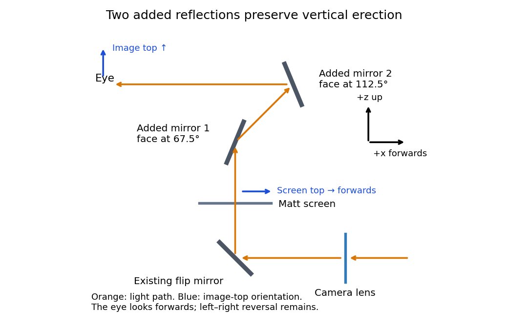
An original vertical-section ray construction with the minimum two added plane mirrors
. Details. 
Use a converging thin lens as a magnifying glass, with the screen at or just inside its front focal plane. It presents an upright virtual image at infinity or at the eye's near point, respectively. Let the near point distance be ; the conventional numerical assumption is , which is not specified in the paper.
Under the usual approximation that the eye is close to the eyepiece, interpreting as the focal length gives the familiar angular magnificationsThe first is for a relaxed eye with the screen at the front focal plane. For the second, the virtual image is at signed distance and the thin lens equation gives screen distance . Thus the often intended maximum requires a screen-to-eye distance of approximately , rather than exactly .
If instead fixes the physical screen-to-eye separation , an eye adjacent to the optical lens sees the angular magnificationThis is achieved by for relaxed viewing, or by for a virtual image at the near point. The latter follows from .
More generally, the source does not specify the eyepiece-to-eye distance either. If that distance is , then and a virtual image at the near point has transverse magnification . Its angular magnification relative to unaided viewing at isFor example, and give , with and . This is a concrete counterexample to a universal maximum of at fixed screen-to-eye separation. In ideal geometrical optics, allows arbitrarily large with an arbitrarily short focal length; practical aperture and optical aberrations constrain this. A unique numerical maximum therefore needs the conventional near-eye eyepiece geometry and near point assumption. The conventional answer is , with those assumptions stated explicitly.
Let be the drop in electric potential along the positive electric charge's path. By conservation of energy, , so the nonrelativistic exit speed is . Apply a uniform magnetic field perpendicular to the incident velocity and to the desired orbital plane. The magnetic Lorentz force is perpendicular to the velocity, does no work, and supplies the centripetal force:For example, and give initial deflection along for positive . Reversing the magnetic field reverses the bending. A uniform electric field alone would give constant acceleration and a parabolic path, not uniform circular motion. The displayed result assumes ; the exact relativistic momentum relation would give .
Add a uniform electric field satisfying . Then the Lorentz force vanishes for the desired velocity. With the axes used above, , perpendicular to both and , withThe crossed fields form a velocity selector. All particles must first have traversed the same electric potential difference from rest: that is what converts selection of speed into selection of charge-to-mass ratio. Equal charge-to-mass ratios yield equal speeds even if the separate masses and charges differ. For other ratios, the initial transverse force is and is nonzero.
Use sinusoidal phasors with physical values , , and . The complex impedance is : its modulus is the voltage-to-current amplitude ratio, and its complex argument is the voltage-minus-current phase difference. Here is the electrical resistance part and the signed electrical reactance; the source's notation differs from the common notation.
The component laws , and give the complex impedances of an ideal resistor, inductor and capacitor:In a series circuit the same electric current flows through both components, so Kirchhoff's voltage law adds their voltage phasors. The resulting series RC impedance isFor positive , the negative phase difference means that electric current leads the applied electric potential difference.
In the parallel LC circuit both components have the same voltage phasor. Adding their current phasors by Kirchhoff's current law gives the total electrical admittance:ThusAt the ideal parallel resonance, , the two branch current phasors cancel. The net electrical admittance is zero and the magnitude of the complex impedance tends to infinity: the parallel combination behaves as an open circuit at that frequency. Its complex argument is undefined exactly at the pole. Finite component losses replace the infinite peak by a large finite electrical impedance. This conclusion concerns a voltage-driven sinusoidal response; an ideal resonant current drive does not have a bounded sinusoidal steady-state voltage.
In SI units, the Maxwell equations in vacuum with prescribed charge density and current density areWhen and , take the curl of the third equation and substitute the fourth. Using the curl of the curl identity and gives the electromagnetic wave equation:For example, , is a plane electromagnetic wave provided . The electric field, magnetic field and propagation direction are mutually perpendicular.
The Maxwell equations are linear, so the superposition principle applies to fields. However, the Poynting vector is quadratic:One may add the average wave intensities only when the cross terms vanish under the actual detector average. For co-propagating plane electromagnetic waves of parallel linear polarization, averaging over optical cycles but potentially resolving the difference frequency givesIf the detector integrates for , the last term acquires , with sinc function convention , evaluated at the midpoint phase. Thus suppresses beats, and the infinite-time average adds the wave intensities exactly for distinct fixed frequencies. Random mutually uncorrelated wave phases also remove the cross terms in an ensemble average; orthogonal linear polarizations remove them for co-propagating waves in polarization-insensitive detection. Merely having different frequencies does not remove a resolved beat signal: two nearly equal frequencies with fixed relative wave phase are a concrete counterexample. For different propagation directions, the relevant addition is of average Poynting vectors, or their components through the chosen detector surface.
For a sinusoidal plane electromagnetic wave in vacuum, write the maximum electric field as . The magnetic field maximum is , so the cycle-averaged Poynting vector magnitude, or light intensity, isEach photon carries energy , where is the Planck constant. Therefore the photon number flux density, namely the number per unit normal area per unit time, isMultiplying by an illuminated normal area gives the photon arrival rate. Each absorbed photon transfers momentum at normal incidence, giving the radiation pressure on a perfectly absorbing surfaceThese are time-averaged quantities. At oblique angle of incidence , the normal radiation pressure is ; the simple displayed expression assumes normal incidence.
The phrase “image” does not specify whether a real image or a virtual image is required. The later mention of an image plane makes a projected real image a natural interpretation. Let be object distance and real-image distance from a converging thin lens. A transverse magnification of magnitude gives , and the object-to-image separation gives . HencePlace the optical lens beyond the object along the illuminating beam. The real image is inverted and has transverse magnification .
For the alternative single-optical lens magnifying glass interpretation, the virtual image is upright and lies on the object's side, so signed . Its separation from the object is . The thin lens equation then givesThe source does not explicitly select between these two geometries; they should not be conflated with a lens-to-image distance.
Use the principle of dark-field microscopy: block the unscattered beam where it is concentrated, while transmitting most light scattering at nonzero angles. All direct light rays of the collimated illumination are parallel, so the thin lens focuses them to one point in its back focal plane. Put a small opaque circular stop centred on that point, one focal length behind the optical lens. In the real image geometry above this is behind the optical lens, well before the real image at .
A light ray leaving object coordinate with a small initial direction reaches the optical lens at . The thin lens changes its direction to . At the back focal plane its coordinate is thereforeThus direct illumination with is concentrated at the centre, whereas scattered light at different directions is distributed away from it, independently of . A stop of radius removes approximately ; choose it just large enough to cover the direct beam's finite diffraction spot, illumination divergence and alignment errors. Scattered light inside that small angular cone is also lost, so negligible loss requires most useful scattered light to lie outside it. A stop in the object's real image plane instead removes object detail and does not generally separate scattered and direct light. For the virtual image interpretation, the same physical back focal plane filtering requires a downstream observation arrangement that actually passes through this plane.
The wavelength at is . For an ideal circular aperture of diameter , the Rayleigh criterion places one source at the first minimum of the other's Airy disk:The customary full-ring packing estimate for the number of resolvable positions in a geostationary orbit isThis is an ideal angular-packing estimate. It identifies apparent angular spacing with spacing around the orbital ring and disregards Earth's occultation and station location. An individual ground station cannot see the whole ring; exact conversion from orbital longitude to sky direction requires its location and the orbital radius. Also, a practical tapered antenna illumination changes the ideal circular-aperture response.
A distant satellite supplies an approximately collimated incident beam. A concave spherical mirror of radius of curvature has paraxial focal length . Put the receiving feed at the principal focus, on the optical axis in front of the dish:The radius of curvature relation is a paraxial approximation. A practical dish is usually a parabolic reflector, which focuses an on-axis collimated beam without spherical aberration; a literal spherical dish has spherical aberration, so an exact optimum over its full aperture would need a specified focusing criterion.
Two nearby directions separated by focus at transverse separation . To avoid a receiver covering both geometric image centres at once, its diameter should not exceed this separation along the orbital direction:This is the usual receiver-size estimate from angular resolution. The Airy disk first-minimum diameter is , but that is a spot-size definition, not the same as the receiver's allowed angular acceptance. At the Rayleigh criterion, the images already overlap; integrating over a finite receiver further reduces contrast. Consequently is an order-of-resolution upper scale, not a sharp universal boundary for a specified signal discrimination probability. A detailed limit would require the receiver response and a resolving criterion.
Use a two-element radio interferometer: couple two small dishes coherently and align the projected baseline along the angular separation of the neighbouring satellites. Each dish's broad antenna response should include both satellites. Match the electronic delays so that the desired satellite arrives in phase at the combiner. For baseline length perpendicular to the central line of sight, a small angular displacement produces geometric path difference and phase differenceFor equal signal amplitudes from one source, the output wave intensity is . Put one satellite on a maximum and its neighbour on the first null: . The smallest useful projected baseline is thereforeThe angles here are measured near the normal to the baseline. At a general pointing angle , replace in the small-separation estimate by . Longer odd-half-fringe baselines can also null the neighbour but create more angular ambiguity. This arrangement provides discrimination along one direction; two collectors alone have repeated interference fringes and do not produce an unambiguous full image.
The signal phase velocity in the coaxial cables is , so the guided wavelength is . The excess cable length is , adding a relative delay of and a relative wave phase of magnitudeLabel the two inputs so that the first configuration has total phase difference , where is the geometric phase difference. Swapping the unequal cables reverses that added wave phase, giving . For the same single-source received wave intensity in each arm,The two interference patterns are shifted by half a fringe: maxima in one are nulls in the other. At broadside both give , so swapping does not change the strength of every possible source. For small angles, the maximum-to-maximum shift is with the chosen baseline. Near broadside, the maxima of configuration A occur near and those of B near ; the signs are exchanged if the input labels are reversed. Independent satellites contribute separately according to these directional gains; their mutually uncorrelated signals should not be added as coherent amplitudes.
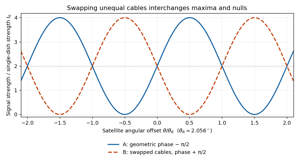
Calculated complementary two-dish signal strengths before and after swapping quarter-wavelength-delay cables
. Details. 
Let the original cylinder axis be , and let the hole axis be at transverse vector , with . The charge density is reproduced by a full cylinder of radius and charge density , superposed with a cylinder of radius centred at and charge density . This uses the superposition principle for fixed insulating electric charges; the hole is not a hole in an electrical conductor.
For a complete uniformly charged infinite cylinder of radius , a coaxial Gaussian surface of length gives, by Gauss's law,Consequently defineThe complete electric field, including the exterior if desired, isIn the insulating material, and , soInside the hole both contributions use their interior formulas, and all dependence on cancels:The electric field in the hole is uniform, points from the original axis towards the hole axis for , and vanishes for a concentric hole. The two expressions agree at the hole wall, as expected with no imposed surface charge density there. Its uniformity is the useful uniform electric field in an off-axis cylindrical cavity result.
Take the grounded electrical conductor to occupy and approximate the negligible-radius charged sphere by a point charge at . Put a fictitious image charge at . The constructed electric potential is zero on , has the correct point charge singularity, and vanishes at infinity. The uniqueness theorem for the electrostatic potential makes it the physical electric potential for :Taking its negative gradient gives the requested electric field outside the small sphere:On the plane at cylindrical radius , the tangential components cancel and the normal component isThe electrostatic boundary conditions at a conductor, with outward unit normal and zero interior electric field, give the induced surface charge densityFinally integrate over annuli of area :The image charge is a computational device, not a real charge below the plane. For a finite conducting sphere, its induced polarization would change the point-source approximation; the stated negligible radius is essential.
The Huygens-Fresnel principle treats every point of an advancing wavefront as a source of secondary spherical waves; their forward envelope constructs the next wavefront. Consider two points where an oblique plane wavefront meets a plane interface a distance apart. After its first point reaches , let time elapse until the second reaches . In medium 1, the incident travel distance is . Meanwhile, a secondary wave from has travelled distance in medium 2. The tangent from to that secondary wavefront gives . ThereforeHere are the angle of incidence and angle of refraction, measured from the interface normal vector, and are the refractive indices at the common frequency. This is Snell's law.
Let be the internal angle of refraction values measured from the two face normals, and let be the external incidence and emergence angles. Geometry of an optical prism gives and total deviation .
For an isosceles optical prism whose internal beam is parallel to its base, reflection symmetry gives . Applying Snell's law at both faces, with air refractive index approximated by one, gives . For transmitted forward rays, , so . HenceThis is the symmetric minimum deviation geometry at a single wavelength. Transmission requires ; otherwise the proposed symmetric path cannot enter and leave through the two faces.
Because optical dispersion makes the refractive index depend on wavelength, no single angle of incidence makes every component of white light travel parallel to the base. Choose the supplied central visible wavelength , with , as the design component. Snell's law givesKeep this angle of incidence fixed for all colours. The other components haveSubstitution givesAll three emerge: the largest value of is about . The angular spread between the extreme supplied wavelengths isThe respective deviations are , and . Applying the symmetric formula independently to the two extreme refractive indices would instead give ; that compares differently oriented optical prisms, not the emerging components of one fixed white-light beam. It can be a rough approximation but misses the stated fixed-incidence geometry. The supplied value is near ultraviolet, so the computed spread refers to the entire supplied band, not a universally defined visible-white spectrum.
A simple converging optical lens bends different wavelengths through different angles because of optical dispersion. For a fixed shape in air, the lensmaker's equation gives : the larger short-wavelength refractive index gives a shorter focal length. Different colours therefore form sharp images at different axial positions, causing longitudinal chromatic aberration, blur and coloured fringes in a white-light image. Off the optical axis, colour-dependent transverse magnification can also give lateral chromatic aberration. An achromatic doublet combines suitable optical glasses and curvatures to reduce this wavelength dependence.
For a circular current loop, the Biot-Savart law iswhere points from a current element to the field point. Choose the loop in the plane, with observation point . A parametrization consistent with positive axial magnetic field isThen andThe transverse contributions cancel around the circle, leaving the on-axis magnetic field of a circular current loopThe right-hand rule fixes its direction; reversing the electric current reverses the magnetic field. At the centre this becomes , and far away it decays as , as expected for a magnetic dipole.
Model the uniformly wound air-core solenoid as coaxial circular turns with solenoid turn density . Put its ends at and an internal axial point at . By the superposition principle, integrating the on-axis magnetic field of a circular current loop givesSince , this evaluates to the on-axis magnetic field of a finite solenoid:The source's acute endpoint angles satisfy and . HenceAlthough the paper calls this a “flux”, is magnetic flux density, measured in teslas. Magnetic flux is an surface integral , measured in webers, and cannot be assigned to a point. For example, two differently sized small disks at the same point have the same limiting but different magnetic fluxes, approximately times their normal areas. The displayed plus sign uses the internal-point angle convention shown in the source. Outside the coil, the integral expression still works, but one must retain signed axial projections rather than adding two acute-angle cosines.
Articles by others on the same topic
There are currently no matching articles.