In Fresnel diffraction, the propagation wave phase varies quadratically across the aperture and that curvature must be retained. For a transverse scale at propagation distance , its size is of order . In Fraunhofer diffraction, that quadratic term is negligible, approximately , while the linear phase encoding the observation angle remains. A lens can also form the far-field angular pattern in its focal plane.
For a normally incident plane wave and aperture transmission , the far-field complex amplitude is its Fourier transform:The detected light intensity is proportional to . For identical parallel slits, write the transmission as a sum of shifted copies of one slit. The Fourier shift theorem gives one single-slit transform multiplied by the sum of positional phase factors:The single-slit diffraction envelope sets the broad scale, while coherent interference between slit centres produces the finer array pattern. One sums complex amplitudes before squaring, rather than adding independent slit intensities.
Put the slit centres at . Each slit has the same width and illumination. Its contribution to the Fraunhofer diffraction complex amplitude isThe four phase factors pair into cosines:Therefore the four-slit Fraunhofer diffraction field isThe common factor can be absorbed in the proportionality constant, giving the requested form. In particular , as expected from four equal in-phase slits. Normalizing by the central intensity givesThe last form follows from and avoids apparent singularities in the usual sine-ratio array formula.
Let be horizontal position on the screen, , and use . The plotted interval is . With , and , the four-slit Fraunhofer diffraction intensity is the previous normalized expression evaluated at this angle. The total aperture width is , giving a Fresnel number of order , consistent with the far-field approximation.
Nominal principal array directions satisfy . Their screen positions areThus the visible nonzero orders are near , in addition to the central maximum. The even nonzero orders are missing diffraction orders: at the first envelope zero occurs at . The next envelope zero and direction lie at about , just beyond the screen edges.
At the nominal first and third array directions, and , respectively. The closest central minima satisfy , hence . Two small subsidiary array maxima occur between adjacent principal directions. The single-slit envelope slightly shifts the true off-axis maxima relative to the nominal principal array angles.
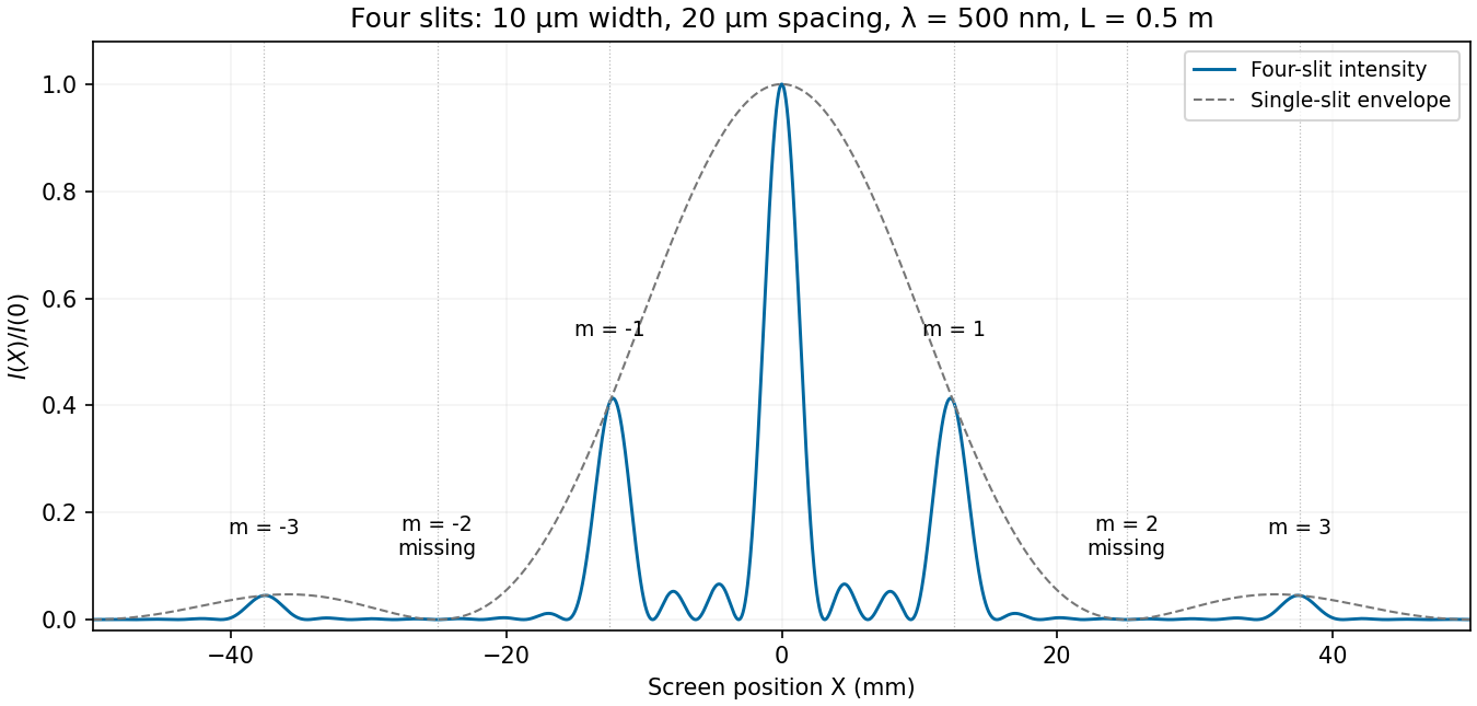
Calculated four-slit intensity across the specified screen, with principal array directions and missing orders marked
. Details. 
Model the two openings as identical axis-aligned rectangles of width in , height in , and centre separation along . Their Fraunhofer diffraction field has the formThe original image shows first broad envelope zeros near and . The horizontal interference period is about ; the first interference minima near distinguish that fine scale from the envelope. The rectangular-aperture dimensions from diffraction zeros are thereforeThe edge-to-edge gap is . The long direction is vertical. These dimensions also explain the suppressed alternate principal array maxima: .
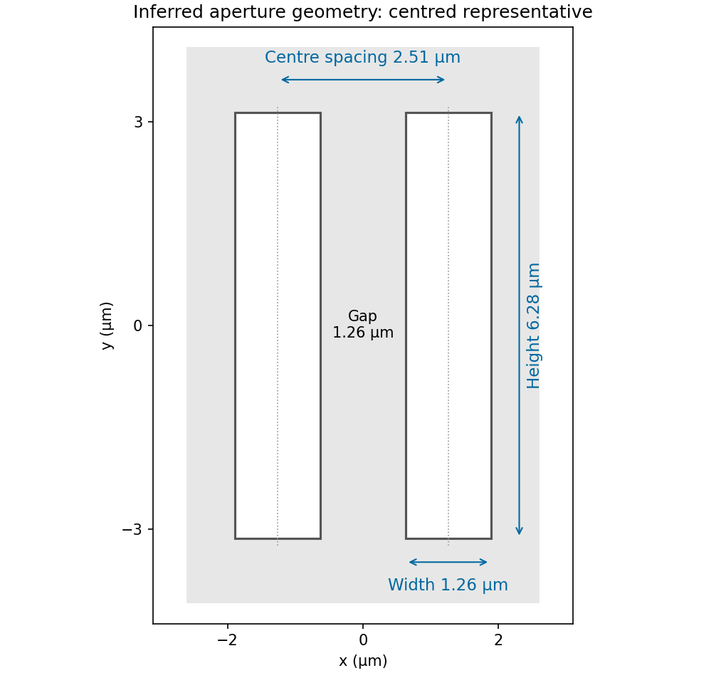
Inferred pair of rectangular openings, quantitatively labelled using the original angular-spatial-wavenumber axes
. Details. 
The factors are required by the stated convention; treating the plotted coordinates as cycles per micrometre would give different dimensions. The finite printed figure supports approximate dimensions. An overall translation and inversion of the aperture pair leave its Fourier intensity unchanged, so their absolute placement is not recoverable; the diagram chooses a convenient centred representative.
Articles by others on the same topic
There are currently no matching articles.