Fresnel diffraction describes diffraction when the quadratic propagation wave phase across an aperture must be retained. Its Fresnel propagator becomes the Fraunhofer diffraction description when that curvature is negligible.
A Fresnel diffraction pattern is a map of how propagation changes the wave interference of light from an aperture. It can resemble the opening, develop bright and dark structure near its edges, and eventually approach a Fraunhofer diffraction pattern. The controlling comparison involves wavelength, opening size and propagation distance together; a distance large compared with the opening need not give the far field.
For a monochromatic wave, use time dependence , wavenumber and complex amplitude . Let be the transmitted field immediately behind an aperture in the plane . In a homogeneous medium, the scalar paraxial approximation givesThis is the two-transverse-coordinate Fresnel propagator, with its carrier restored. It adds complex amplitudes before taking their squared complex modulus to obtain light intensity. It is a scalar paraxial approximation, rather than a full vector solution of Maxwell equations.[ref]
Scalar Diffraction Optics. Interactive Optics by Sander Konijnenberg, Aurèle J.L. Adam and H. Paul Urbach; Fresnel Approximation, equations (381)–(385), and the following paraxial-wave-equation remark
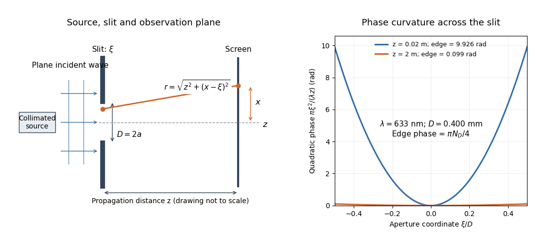
The source in this constructed geometry supplies a plane wave; the observation screen is a plane perpendicular to the optical axis. The right panel isolates the aperture-dependent wave phase that distinguishes Fresnel diffraction from Fraunhofer diffraction. Its vertical scale is in radians, and the drawing's lengths are schematic.
Keeping this wave phase is useful when transporting a field between nearby optical components: both the shape and the complex amplitude matter for subsequent wave interference. A particularly striking feature is that propagation can create a dark centre even from a uniformly illuminated symmetric aperture; the incident wave amplitudes need not be unequal for their outgoing contributions to cancel.
For normalized Fresnel integrals , an interval aperture contributes the chord between its two limiting points on the Cornu spiral. The full unobstructed field is , so its squared magnitude is2. Comparing to only the half-plane limit instead of this full chord introduces a factor-of-four normalization error. The formula compares power at one observation point under the same illumination and propagation factors.
The largest radius of the normalized Cornu spiral occurs on its first outer turn at , where . Oddness makes the chord from to attain twice that radius, while the triangle inequality bounds every other chord by the same length. The interval is therefore the strongest freely selectable connected aperture at that observation point, with normalized point power about1.80142. Signed physical limits follow from . Existing openings can constrain this optimization.
If a screen already has an interval hole, additional removal cannot reduce that hole. A connected final aperture must contain it, imposing lower/upper endpoint constraints on its Cornu spiral chord. The unrestricted longest chord need not be feasible. For an existing interval , constrained chord maximization gives approximately , , with point-power ratio1.60257. The two aperture endpoints, rather than just a nominal Fresnel-zone width, determine the received field.
For an opaque half-plane whose edge lies height above the direct source–receiver ray, the paraxial parameter is . The unobstructed half-aperture supplies the Cornu spiral chord from to infinity. Division by the full-aperture chord gives the displayed intensity transmission. It is at grazing incidence, approaches one well into the illuminated region and tends to zero deep in shadow.[ref]
A diffraction-loss ratio is normalized to the unobstructed intensity at the same receiver position. With a point source that unobstructed intensity changes as inverse source–receiver distance squared. Moving the receiver can therefore decrease the transmission ratio while increasing its absolute received intensity. The two curves require separate normalization; a Cornu-chord plot alone omits geometric spreading.
A scalar aperture approximation that sums the secondary waves reaching an observation point. For a point source with incident spherical amplitude , one common forward-normal convention isHere and are source-to-aperture and aperture-to-observer distances and is an obliquity factor. The Fresnel diffraction approximation retains quadratic path phase; Fraunhofer diffraction additionally neglects the quadratic phase across the aperture. Kirchhoff boundary assumptions do not give an exact electromagnetic solution at a sharp edge.
A concentric diffractive focusing element with successive zone boundaries chosen to differ by half a wavelength of optical path to a focus. Alternating transmitting and absorbing zones suppress cancellation between neighboring half-period zones. For an incident plane wave, the paraxial boundaries satisfy . The outermost zone width controls the finest transverse scale, and the focal length varies with wavelength.
For a plane wave incident on a flat zone plate, the path difference from radius to axial focal distance is . Setting it equal to gives the title relation. The paraxial limit is , and the fine outer-zone width is approximately . Alternately removing half-period annuli makes the remaining contributions reinforce at the principal focus. Choosing the number of zones sets the aperture and fabrication scale, not the principal focal distance independently of these radii.
For uniform coherent plane-wave illumination, an ideal binary amplitude zone plate transmits alternate Fresnel half-period zones. If complete odd zones are open, every one contributes approximately twice the unobstructed axial complex amplitude, in the same phase, and . This is a local light intensity gain relative to removing the plate and outer stop. It differs from comparison with a finite clear aperture: an aperture containing an odd integer number of half-period zones has axial intensity , giving plate-to-aperture ratio . Neither gain is a total power efficiency.
At the geometric shadow boundary of a straight opaque half-plane, the transmitted Fresnel integral is exactly half the unobstructed complex amplitude for ideal point illumination. The Cornu spiral chord is from its origin to one limiting endpoint, rather than between both limiting endpoints. Therefore and . Half the unobstructed intensity would confuse a field fraction with its square. Edge thickness, source extent and alignment can modify the ideal result.
The Arago spot is the bright axial point in the shadow of a circular obstruction under suitably coherent illumination. In ideal scalar diffraction theory, secondary fields from the circular edge arrive in phase on axis. Fresnel diffraction by an opaque disk gives an axial intensity equal to the unobstructed intensity in its paraxial model; this is not a claim that the whole geometric shadow is bright.
Under the same scalar paraxial assumptions as Fresnel diffraction by a circular aperture, Babinet's principle gives the complementary opaque-disk field on axis. Its axial intensity equals the unobstructed intensity, producing the Arago spot inside the geometric shadow. The off-axis pattern depends on the full Fresnel integral; it is not obtained by subtracting aperture intensities from the incident intensity. Finite source size, misalignment and imperfect circular edges reduce the ideal spot contrast.
For a circular aperture of radius , paraxial plane-wave illumination and propagation distance , define . On axis, the radial Fresnel diffraction integral normalized by the unobstructed field givesFor a finite axial point source a distance before the aperture and detector a distance after it, replace by in the phase. The formula assumes illumination amplitudes and obliquity factors approximately constant across the aperture. Odd and even numbers of Fresnel half-period zones give bright and dark axial extrema; large local intensity is compatible with global conservation of energy.
A Fresnel half-period zone is a region of an aperture whose optical path to an observation point differs from the axial path by an interval of half a wavelength. For an axial optical point source a distance before the aperture and an axial observer a distance beyond it, the paraxial path excess at aperture radius is . The outer radius of zone is thereforeSuccessive zones contribute approximately opposite phases to the Huygens-Fresnel principle integral. The finite source distance matters: using the plane-wave formula requires .
For an axial point source a distance before a square aperture and an observer a distance beyond it, source and observation wave phase curvatures add: . With aperture side , put . Separation into two one-dimensional Fresnel integrals gives the field normalized to its unobscured value,At an off-axis observer , centre the dimensionless coordinates on and . If are the directed Cornu spiral chords between the corresponding aperture-edge parameters, . This is a product of complex interval factors, rather than a sum of two intensities. The unobscured field is evaluated at the same observation point and includes its common propagation wave phase.
The quadratic wave phase follows from an ordinary distance calculation. Write . The Taylor expansion of the distance to a screen point isIn the slowly varying propagation prefactor, suffices. In the complex exponential , however, a small distance error is multiplied by the large wavenumber . Retaining the quadratic term while dropping the quartic term requires both and over the contributing aperture and the screen region being considered. The second condition is a wave phase accuracy requirement; the first is the geometric paraxial approximation.
Expanding the retained quadratic term separates three effects:The outside quadratic factor changes the wave phase at each screen point but has unit complex modulus, so it leaves that screen's light intensity unchanged. The quadratic factor inside the integral changes relative wave phases between contributions from different aperture points, so it changes their wave interference. The remaining linear factor supplies a Fourier transform. Fraunhofer diffraction drops the aperture quadratic factor when it is nearly constant; it does not require dropping the screen quadratic factor when predicting a later coherent field.
There is also a useful proof from the Helmholtz equation. Substituting gives . Neglecting yields the parabolic wave equation. A transverse Fourier transform evolves each spatial frequency by , using the transform kernel . Its inverse Fourier transform is the quadratic Fresnel propagator kernel above. Thus quadratic wave phase in space and quadratic wave phase in spatial frequency are two views of the same propagation.
A Fresnel number compares squared aperture size with the product of wavelength and propagation distance. For an optical slit of full width , explicitly distinguish the full-width and half-width conventions:The full-width convention is used throughout the Fresnel slit propagation example below. The definition also appears in the Delft treatment.[ref]
Scalar Diffraction Optics. Interactive Optics by Sander Konijnenberg, Aurèle J.L. Adam and H. Paul Urbach; Fresnel and Fraunhofer Approximations, equations (390)–(392): aperture diameter convention
For uniform incident wave phase, makes the omitted aperture wave phase small and gives the Fraunhofer diffraction regime. When is of order one or larger, retain it and use Fresnel diffraction, provided the paraxial approximation still holds. These are continuous changes in accuracy, rather than a physical boundary at one selected number. For a rectangular aperture, check both transverse dimensions. Incident wavefront curvature contributes its own wave phase through ; the aperture-to-screen Fresnel number alone does not describe a spherical source's illumination.
The scaling is revealing: doubling the optical slit width at fixed wavelength and distance multiplies the Fresnel number by four. Maintaining the same Fresnel number then requires four times the distance. Two systems can consequently have the same dimensionless pattern despite very different physical lengths.
Consider a uniform plane wave of unit complex amplitude transmitted by an ideal optical slit of full width . Treat the field as invariant along the optical slit height: this is one-dimensional transverse Fresnel propagation, so the prefactor is , rather than the two-dimensional prefactor . Removing the carrier givesHere is incident irradiance. This infinitely long slit model describes a transverse cut away from the ends of a sufficiently long physical slit; its finite conserved quantity is transmitted power per unit optical slit height.
Put and . Substitution reduces the integral toThis form separates the pattern's shape from its physical scale. Reflection proves , so the light intensity is an even function of . At , direct integration gives , with limit one at . Hence the Fraunhofer diffraction comparison is the squared sinc function. In this paragraph the unnormalized sinc function takes argument .
For an original example, choose wavelength and full width . At , , and the edge-to-centre wave phase change is radians. At , , and that wave phase change is only radians. Even the nearer screen is fifty slit widths away; that geometric comparison alone misses its strong Fresnel diffraction.
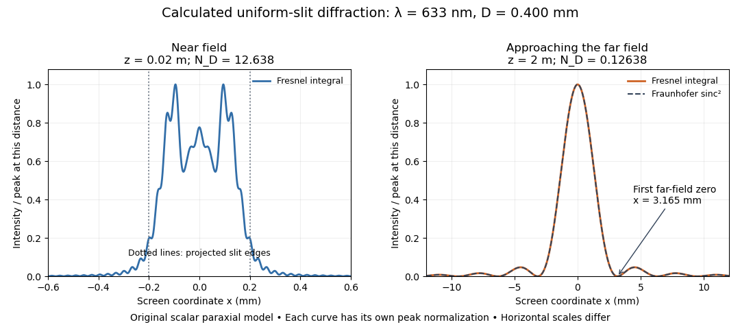
Original calculated Fresnel diffraction profiles of a 0.400 mm slit at 633 nm, compared with the Fraunhofer diffraction shape
. Details. These are numerical predictions from the displayed scalar integral, using the composite trapezoidal rule, rather than measured profiles. Each curve is divided by its own peak light intensity; the two horizontal scales differ. At 2 cm the computed central irradiance is about , with brighter off-axis maxima. At 2 m it is about and is the peak. The dashed Fraunhofer diffraction curve has its own central normalization; its first zeros are at . The finite-distance Fresnel diffraction curve remains slightly nonzero there.
Normalization hides the brightness change, but not the change in shape. The Fourier transform propagation multiplier has unit complex modulus, so Plancherel theorem givesThis is conservation of transmitted power per unit height in the ideal scalar model. An integral over only the displayed screen interval misses the tails; a peak-normalized profile is not a unit-integral probability density. Spreading and decreasing brightness together preserve the transmitted power.
A documented experiment uses curved illumination rather than the uniform Fresnel slit propagation model. Laboratory Exercise No. 4: Diffraction, MIT 6.237, Fall 2024, printed pp. 5–6, gives a helium–neon laser at , a microscope objective optical lens, a circular aperture and a screen 5–40 cm from the object. Preparation includes comparing central brightness in Fresnel diffraction and Fraunhofer diffraction. A 40× objective produces a nonplanar incident wavefront; the opening is placed less than 1 cm from it. With objective-to-screen distance fixed, students move the opening, sketch patterns, and record positions of consecutive central nulls to estimate aperture size. The Fraunhofer diffraction pattern supplies a regime comparison. A separate spherical-obstacle task observes a bright centre inside the shadow. The handout supplies procedures, rather than measured distances or profiles.[ref]
The circular-opening test probes cancellation of complex amplitudes at the centre while the source wavefront curvature changes. To interpret it, include that curvature in the aperture field and use a circular aperture, rather than substituting the plane-illuminated Fresnel slit propagation profile. Useful additional controls are to retain the same laser and opening, centre the illumination, repeat position readings and check background with the beam blocked. If a camera replaces the visual screen readout, avoid saturation and calibrate its position scale. Alignment, imperfect aperture edges, illumination variation and limited contrast near a null constrain the inferred size. A bright central obstacle spot illustrates why the sharp shadows of geometrical optics can fail; it does not imply that every Fresnel diffraction pattern has a bright centre.
Articles by others on the same topic

Fresnel diffraction is a type of wave diffraction that occurs when a wavefront encounters an obstacle or aperture with dimensions comparable to its wavelength. It is named after the French engineer and physicist Augustin-Jean Fresnel, who developed the theory to better understand the behavior of light.


Near field approximation to Kirchhoff's diffraction formula, i.e. when the plane of observation is near the object diffracting.