The original PDF places this complete question before B6 without a visible question number. It is included here under a descriptive heading.
Why images work. In the method of images, place fictitious image charges outside the region where the physical electric field is required. Choose them so that the combined electric potential satisfies the conductor boundary conditions. The Uniqueness of the Dirichlet problem then proves that this construction gives the physical exterior field. The images do not describe the actual surface-charge locations.
Two examples are a charge above a grounded conducting plane, represented by at the mirror point, and the image charge for a grounded conducting sphere used below. In each case the image lies inside the excluded conductor and makes its surface an equipotential of the required value.
Potential of the two charges. By the law of cosines, the distances from the observation point to charges at are . The superposition principle and Coulomb's law therefore give
The grounded sphere. Set and require at every polar angle. Matching the coefficients of and the constant terms givesThe useful noncoincident solution isIndeed on the sphere, so the two potential terms cancel there. A Gaussian surface enclosing the sphere but not the external charge measures the total image charge in the exterior representation. Thus the physical induced net charge is
An isolated neutral sphere. The grounded image would give nonzero net charge. Add a central image to cancel it. A central image changes the surface potential by a constant, preserving the equipotential condition, whereas an arbitrary off-centre image would generally spoil it. The image charges for a neutral conducting sphere giveThe potential is measured relative to zero at infinity for each finite .
Fixed applied field and dipole moment. For positive on the positive axis, the applied central field is . The central image contributes no electric dipole moment, soIts units are coulomb metres. Keeping fixed makes constant, so this induced moment is independent of the distance.
The distant-charge limit. As with fixed, the applied field becomes uniform over any fixed neighbourhood of the sphere. The neutral pair of opposite images approaches a point dipole of the finite moment above. The external potential contains a growing spatial constant , so the infinity-referenced conductor potential does not have a finite limit. Subtracting this irrelevant constant gives the usual induced charge on a conducting sphere in a uniform electric field; the exterior potential becomesThis has zero potential on the sphere, but a uniform applied field cannot simultaneously have its potential vanish at spatial infinity.
Induction and its sign. The Maxwell-Faraday equation is . For a fixed loop, Stokes theorem givesThis is Faraday's law of induction. The orientation of the surface normal and positive circulation are linked by the right-hand rule. The minus sign is Lenz's law: the induced current's linked flux opposes the imposed flux change, rather than reinforcing it.
The inductive current. Let the loop normal make angle with the applied field, with positive current defined by that normal. The external magnetic flux is . With negligible electrical resistance, the circuit equation is , so total linked flux is constant. For zero initial trapped flux,The printed result needs this initial-flux assumption; in general an additional constant current is allowed. The units are amperes because a weber divided by a henry is an ampere.
Current and forces at one instant. Take along and , so relative to the chosen normal. The loop magnetic dipole moment therefore has a component opposite the applied field. Each wire element experiences Lorentz force . Opposite sides have equal and opposite forces, giving zero net force in the uniform field but a nonzero couple.
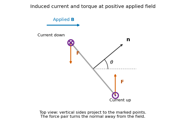
Original top view of the loop's vertical sides at positive applied field; dots and crosses show vertical current, and the force pair increases the angle between normal and field
. Details. 
The horizontal top and bottom wire segments also experience equal and opposite vertical forces. They cancel without adding torque about the vertical rotation axis; the displayed force pair supplies that torque.
Average torque. Since , its generalized component for increasing is . Substitution givesand, using ,The orientation torque on a flux-conserving loop drives its normal away from the field for the stated initial angle. Its magnitude has units joules, or newton metres.
Free motion with large inertia. Write for the mechanical moment of inertia. If its orientation changes little during each field cycle, the slow equation is , with effective potentialThe stable orientation is , where the loop plane contains the applied field. Released from rest between and , the loop accelerates toward that orientation, overshoots and librates around it. In the leading averaged, undamped model its turning angles are and . It does not settle without a dissipative mechanism. For small librations the squared angular frequency is .
Negligible inductance and finite resistance. Now the current is proportional to the induced electromotive force, not to the flux. Including slow rotation,The rotational damping of a resistive loop in an oscillating field follows fromAt fixed orientation, the first term alternates at and has zero mean. The loop can therefore rock slightly, but there is no leading mean aligning torque like that in the inductive case. Slow rotation giveswhich opposes motion and produces Joule heating. Initial-phase transients can initiate motion, and the instantaneous torque is not zero. This description retains the large-inertia, slow-motion approximation; it does not assert an exact stationary solution at every starting angle.
The integral field equation. The Ampere-Maxwell law is . Apply Stokes theorem to any fixed oriented surface bounded by the chosen contour:The added displacement current is required for compatibility with electric charge conservation. Taking a divergence and using gives .
Field geometry. Choose the upper plate positive and let increase upward. In the long-plate, slow-discharge approximation, . Conventional wire current runs downward from the positive plate. The magnetic field intensity circulates clockwise as viewed from above. The Poynting vector points radially toward the resistive wire.
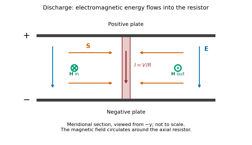
Original meridional section of the discharging capacitor; electric field and wire current point down, magnetic field circles the wire, and electromagnetic energy flows inward
. Details. 
Wire and displacement currents. The capacitance and discharge law areBecause decreases, points upward, opposing the downward wire current. Through a disk of radius between the plates its magnitude isThe effective downward current enclosed by the circular contour is therefore . The Ampere-Maxwell law givesThis is the magnitude; with the stated coordinates, . The factor expresses cancellation between conduction and displacement currents. The approximation requires distances outside the thin wire and away from detailed electrode-edge fields.
Energy flux and power. Since ,Its units are watts per square metre. Integrating over the cylinder's side area , the signed outward power is negative:There is no leading axial flux through the cylinder's ends in this ideal field geometry.
Where the energy goes. The Poynting flux in a centrally discharged parallel-plate capacitor carries field energy through the dielectric space into the resistor, where it becomes Joule heating at rate . Inside radius the stored electric energy isHenceThe resistor receives the inward flux from outside that cylinder plus the field energy released inside it. As approaches the wire radius, essentially all its power arrives as radial electromagnetic flux. Over the whole capacitor, . The Poynting theorem thus accounts for the complete discharge without treating energy as transported only along the conducting wire. High resistance makes the quasistatic electric-field approximation and neglect of changing magnetic energy consistent.
Two interface effects. For , Snell's law gives . If , no propagating transmitted ray exists: there is total internal reflection, with an evanescent wave on the far side. An optical fibre uses this to guide light.
For ordinary isotropic nonmagnetic media, is the Brewster angle. The reflected p-polarized component, whose electric field lies in the incidence plane, vanishes; the reflected s-polarized component generally remains. Reflection polarizers and polarized glare reduction exploit this selectivity.
The plasma response. Neglect collisions, thermal-pressure corrections and background magnetic field. Let the wave vary as . An electron displacement obeysIts dipole moment is , so the electron electric polarization is . Ions of charge give a further contribution , smaller by . Thus heavy ions move negligibly at these electron-wave frequencies. Using gives the cold collisionless plasma dielectric response,For this model , so and for the transverse electromagnetic wave.
The vertical cutoff and density. Below the plasma frequency, the squared refractive index is negative: the wave is an evanescent wave instead of propagating through a layer hundreds of kilometres thick. The observed cutoff therefore identifies , with . ConsequentlyThis uses , and . The density is also .
The transmission elevation. At , the ionosphere has refractive indexIf is elevation above horizontal, incidence at the layer is . Avoiding total internal reflection requires . The limiting elevation is thereforeStrictly, it must point above this limiting angle to carry upward power through the finite layer: at equality the transmitted wave is grazing. With a suitable satellite position, the stated orbital altitude imposes no additional angular constraint in this flat-layer approximation.
Polarization-selective ground reflection. The ray's incidence plane is vertical. Horizontal electric polarization is s polarization; the other transverse polarization lies in the vertical incidence plane and is p polarization. Reflection of s but not p identifies the Brewster angle, not total internal reflection, which would reflect both in this lossless isotropic model. ThusFor a reflecting height , the horizontal range consists of two equal legs. The Brewster reflection from an ionospheric interface givesAt this angle is below the critical incidence angle, so a transmitted ray also exists; the detected horizontal component is an ordinary partial reflection. The s-polarized reflected power fraction is approximately , whereas the ideal p-polarized reflected fraction is zero. These results use the question's sharp planar interface model and exclude upper-interface reflections.
Articles by others on the same topic
There are currently no matching articles.