For the supplied linear meter model let and . If the applied step is , the settled deflection is . An underdamped response overshoots and rings about that value; a critically damped response reaches it monotonically without ringing; an overdamped response is also monotone from these initial conditions but has a slower final approach. The original plot uses the common final value and natural-frequency time scale.
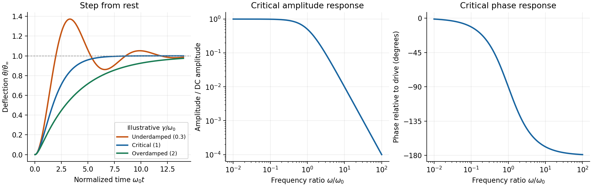

The critical step response of a galvanometer has and repeated homogeneous root . Apply to the general constant-force solution to obtainIts derivative is , with the sign of the step. It is the fastest nonoscillatory response within this second-order family at fixed , avoiding a needle that repeatedly crosses the reading or an unnecessarily slow overdamped settling.
For sinusoidal drive choose phasors. Writing , the response amplitude isFor positive , choose the continuous lag branch from zero to as frequency increases; an ordinary single-argument arctangent without the quadrant would give the wrong high-frequency phase.
For the critical galvanometer transfer function, the denominator factors as . ThusFor , the meter follows the quasi-static deflection with a small lag . For , its amplitude is and its lag approaches .
The stated components give s⁻¹ and, if critical, rad/s, or Hz. At 50 Hz, rad/s andThe needle barely responds compared with its DC sensitivity and its mean deflection for a pure sinusoid is zero in this linear model. It is unsuitable for directly measuring 50-Hz amplitude or RMS current without an additional rectifier or another readout method. The calculation treats as the stipulated torque/back-emf coefficient of the given equation; it does not infer an unprovided winding geometry.
Use phasors. The relation gives . The three branches form a parallel RLC circuit and share the source voltage. The source-current phasor and its real time dependence areConsequently its amplitude is and its phase relative to the voltage is . At low frequency it is inductive and lags toward ; at high frequency it is capacitive and leads toward . The ideal amplitude diverges at either extreme and has a finite minimum between them; real component losses and source electrical impedance limit those asymptotes.
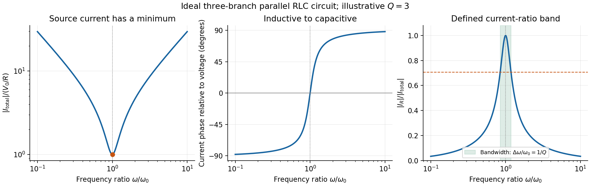
Original normalized source-current amplitude, phase and resistor-to-source-current ratio for an illustrative ideal parallel RLC circuit
. Details. 
Zero phase requires cancellation of electrical susceptances:The inductor and capacitor currents are nonzero, equal in magnitude and opposite in phase, while the resistor supplies the in-phase source current. energy oscillates between the reactive elements; dissipation occurs in the shunt resistor. A source-current maximum would describe a different, series-resonant circuit.
The specified ratio isIt exceeds when . Define and . The two positive endpoints are , soThe endpoints have geometric mean . Increasing the parallel resistance reduces dissipative loading and narrows this band, in contrast with increasing the resistance of a series RLC circuit. Equivalently, , with and . The parallel RLC bandwidth here belongs to the explicitly defined current ratio, not a half-maximum rule applied to a source-current peak that does not exist.
Articles by others on the same topic
There are currently no matching articles.