The moment of inertia about a specified axis is , where is perpendicular distance from the axis. The parallel axis theorem states for two parallel axes separated by , one passing through the centre of mass of a body of mass .
It is easiest to calculate the eccentric disc by subtraction. Let be the mass of the unperforated disc and the removed mass. Uniform thickness and density give and , hence and . The hole is tangent to the rim, so its centre, and therefore the shaft axis, lies from the original disc centre. About the shaft axis,The shaft contributes . ThusThe motor's torque is at nonzero angular velocity, while the resisting torque is . The rotational equation of motion and its equivalent energy balance areAt the steady state, input power equals dissipated power, givingFor the acceleration, use . Then with , soThe approach to takes infinite time. This constant-power rotational acceleration idealizes the start: diverges at rest, although the energy balance has a well-defined limiting solution. A real motor has finite starting torque.
Conservation of energy states that the total energy of an isolated system is constant. In a mechanical problem with conservative forces and no dissipation, it gives . It often determines a speed or turning height directly, without solving the full time-dependent equation of motion. With external work or dissipation, use the corresponding energy balance instead.
After a drop leaves the wheel, neglecting air resistance, the conservative force of the Newtonian gravitational field acts. Put the origin at the wheel axis and choose positive horizontal displacement to the right. In the printed diagram is measured upward from the leftward horizontal radius, and rotation is clockwise. The release position and velocity are thereforeFor upward release, . These conventions fix the signs used below.
With zero gravitational potential energy at the wheel axis, the release energy and the energy at the apex of the projectile motion areOnly the vertical velocity vanishes at the apex: the horizontal kinetic energy remains. Equating the two energies gives
Set . The maximum height becomes the concave quadratic functionUnder the stated high-angular frequency assumption, , its interior maximum isThus the optimum release lies on the upper-left quarter of the wheel for the printed clockwise rotation. The largest attained height isIf extended to , the maximum over release positions is the limiting height at the top of the rim. The interior solution is the relevant branch for reaching a ceiling above the wheel.
To avoid contact with the ceiling, require . Writing giveswhose roots are . Because , the lower root is less than , while the assumed branch has . The lower inequality is therefore automatic on this branch, leavingEquality is the first grazing contact. This branch check is essential: retaining both algebraic roots as independent lower and upper speed limits would introduce a spurious lower limit on avoiding the ceiling.
At first contact the globally highest trajectory just touches the ceiling at its apex. Its flight time to that point is . The horizontal displacement from the wheel axis isHence the first point struck is directly above the rotation axis, independently of . The release starts to the left of the axis, but the drop's horizontal travel exactly cancels that offset at the optimum apex. The first-contact angular velocity satisfies .
The Michelson-Morley experiment splits coherent light into two perpendicular arms, reflects the beams and recombines them to observe interference fringes. Rotating the apparatus interchanges each arm's orientation relative to a proposed stationary luminiferous aether. The historical experiment used multiple reflections to increase the effective optical path and a rotatable support to compare orientations.[ref]
On the Relative Motion of the Earth and the Luminiferous Ether by Albert Abraham Michelson and Edward W. Morley. 1887, printed pp. 333–341: optical arrangement, rotation and fringe-shift comparison
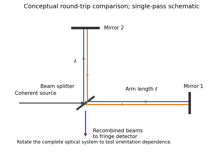

For equal one-way effective arm lengths , a classical stationary-aether model givesA right-angle rotation should reverse their difference, producing a fringe shift of approximately . The observed orientation-dependent shift was much smaller than the stationary-aether prediction. In special relativity, the apparatus rest frame has the same vacuum speed of light along both arms, so no such orientation-dependent shift is expected. The result supports special relativity but does not, by itself, uniquely establish every postulate or exclude every modified aether theory.
For the rocket, take its tail at and nose at , with coincident frame origins when . Denote emission, reflection and return by . In the rocket's inertial frame, their coordinates areThe inverse Lorentz transformation is , , where . Thus the same spacetime events, in coordinates , areThere is no requirement that emission have in this chosen laboratory coordinate system.
The nose-to-tail travel time is . If is the laboratory length measured at one laboratory time, a left-moving pulse and the right-moving tail close their initial separation at speed . ThereforeThis derives length contraction from the pulse's travel. Comparing the positions of the two endpoints at different laboratory times would not measure the rocket's laboratory length.
Articles by others on the same topic
There are currently no matching articles.