A D flip-flop stores one bit. At its specified active clock edge, it samples and, after its clock-to-Q delay, makes equal to that sampled value. Between active clock edges it retains the stored value. The input must meet the setup and hold time requirements around the sampling edge; a level-sensitive latch would have different behavior.
For a finite-state sequential circuit, encode the present state in a bank of D flip-flops. Feed their outputs and the external inputs to combinational logic computing the next-state function , and connect those outputs to the flip-flop inputs. A common clock signal then performs the simultaneous updateOutput combinational logic computes for a Moore machine or for a Mealy machine. Since any finite next-state and output table is a Boolean function, it has a Boolean circuit implementation. Initialization specifies the starting state, and unused state encodings require either a recovery rule or an initialization assumption. The clock period must accommodate propagation through the D flip-flops and intervening combinational logic before the next sampling edge.
A particularly transparent design uses six D flip-flops in a one-hot encoding. Let mean that face is displayed. Initialize and , and wire the next-state inputs as a ring:All six D flip-flops share the same active clock edge. Each pulse moves the single stored to the next position, giving the state-transition diagram cycle . The representation invariant “exactly one is high” holds after initialization and is preserved by rotation. Six D flip-flops are more than the three-bit theoretical minimum, but their simple wiring gives a complete implementation without requiring that minimum.
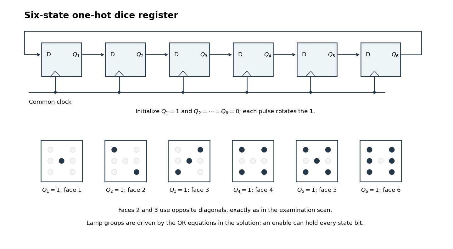
One-hot ring state register and the six lamp patterns, including the original opposite diagonals on faces 2 and 3
. Details. 
Decode the seven lamps by their positions, with denoting top, middle and bottom, and denoting left and right. Let be the center lamp. In the original figure, face 2 uses top-left and bottom-right, while face 3 uses top-right and bottom-left plus center; the two diagonals must therefore have different controls.[ref]
Functional programming, data structures and algorithms, procedural programming, and digital hardware examination paper by the University of Oxford (2005). Printed p. 6, Figure 1(b), faces 2 and 3
The required OR gate decoder isFor example, only the center is high in state , the first diagonal is high in state , and in state both outer columns are high while the center is low. This verifies all six layouts directly.To implement the switch behavior, use a rapid common clock signal and a sampled enable , high while the switch is pressed. Each next-state input is then selected between its advancing value and its own stored value:One multiplexer per D flip-flop implements that selection. While enabled the electronic dice advances; otherwise every D flip-flop reloads its own value and the display holds. The enable supplied to this synchronous design must be stable at sampling edges. A reset or preset facility must establish the specified one-hot initial state: an all-zero ring does not start itself.
With a rapid clock signal, uncertainty in human release timing makes the final face practically unpredictable. The sequential circuit itself is deterministic; this observation alone is not a proof that its six outcomes have equal probabilities.
Articles by others on the same topic
There are currently no matching articles.