The two lower conducting branches are the series pairs controlled by and by . Their overall NMOS transistor conduction condition is . Apply complementary CMOS network duality: the upper network has the parallel pair of PMOS transistors controlled by , in series with the parallel pair controlled by . Its first end connects to the high rail, its last end connects to , and the junction between the two pairs is internal to the upper network.
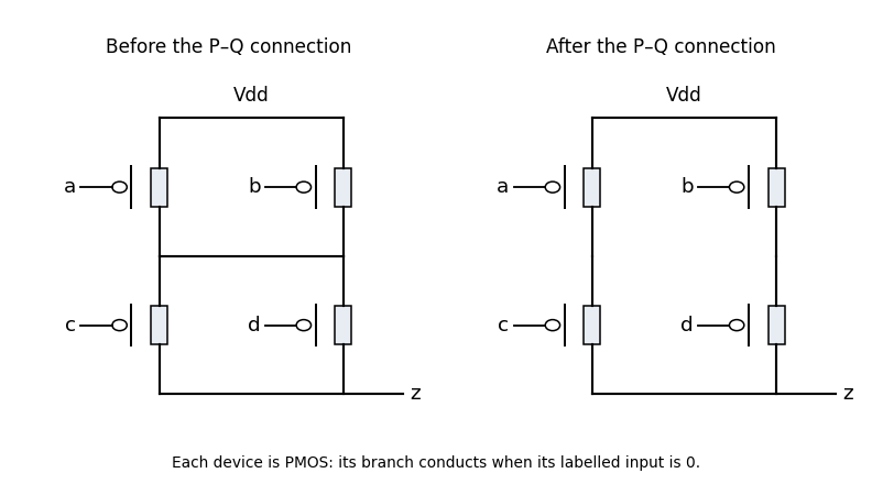
Original completed pull-up networks derived by complementary CMOS network duality
. Details. 
The left panel gives that completion. Every upper transistor uses its correspondingly named input and conducts when that input is low. Its conducting condition is , exactly the complement of the lower condition. Thus the ideal static circuit connects the output to one supply rail for every stable binary input.
The lower network pulls the output low exactly when either series branch conducts. Therefore the Boolean function isThe inversion is important: describes connection to the low rail, not a high output. The pull-up network found in part a implements the complementary high condition.
Joining the two middle nodes makes the upper lower-network transistors, controlled by , parallel with each other. The lower transistors, controlled by , are also parallel. These two parallel groups are in series, so the lower conducting condition becomes .
Its dual upper network must be two parallel branches, one containing the series PMOS transistor pair , the other the series pair . This is the right panel of the original drawing. Its condition is . Merely leaving the old upper network unchanged would break CMOS complementarity for some inputs, allowing a supply short rather than defining the required logic.
The modified output isFor example, gives and . Neither original series branch is complete, but the new connection supplies the cross-route through the transistors controlled by . Interchanging those roles gives the other cross-route example. In fact , so the modified circuit has added exactly those two possible lower conduction routes.
Let be the input sampled at clock edge . The desired registered output after that edge is . Only the last two high samples matter: a longer high run still has two high samples immediately before its first low sample.
A direct synchronous 110 detector uses three D flip-flops, holding , with a common clock and initial state zero. Use the following next-state equations, all evaluated from the old state and the input at the active clock edge:After an edge, records the latest sample and records whether the latest two samples were high. The final equation consequently produces the required pulse from the preceding two-high state and the new low sample. A synchronous reset sets all three state bits to zero. The output is the stored
z flip-flop value, so it changes only after clock edges; exposing the unregistered expression would let input transitions between edges alter the output.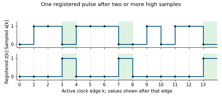
Original sampled-input and registered-output trace for a synchronous 110 detector
. Details. 
An equivalent finite-state machine has states
R (no current high run), H (one high), HH (at least two highs), and P (the pulse state). Its output is one only in P:The pulse cannot last two cycles: after the low input that creates it, is zero, so the next output is zero regardless of the next input. The detector rearms without a global stop and handles repeated patterns indefinitely. The three-flip-flop construction is deliberately direct; minimum storage was not required.
Articles by others on the same topic
There are currently no matching articles.