For an approximately isotropic rock, the P wave and S wave speeds arewhere is bulk modulus, is shear modulus, and is density. Five important controls are:
- Mineralogy and cementation. Stiff, well-cemented mineral frameworks usually have higher elastic modulus values and faster seismic velocities than poorly consolidated sediments. Density alone is insufficient: both stiffness and density enter the equations.
- Porosity and cracks. Larger porosity, especially compliant cracks, usually lowers effective elastic modulus values and seismic velocities. Crack orientation can make the seismic velocities direction-dependent through seismic anisotropy.
- Pore-fluid composition and saturation. Replacing liquid water by gas generally lowers the effective bulk modulus sharply and reduces . Pore fluids have negligible static shear modulus; responds chiefly through the solid framework and the changed bulk density, rather than through a shear restoring force in the fluid.
- Effective confining pressure. Increasing effective stress closes cracks and improves grain contacts, usually increasing both seismic velocities. Increasing pore fluid pressure at fixed total stress reduces effective stress and can reverse this trend.
- Temperature. At otherwise comparable conditions, increasing temperature generally softens minerals and lowers seismic velocities; thermal cracking or partial melting can lower them further. Increasing burial commonly increases both temperature and pressure, so their separate effects need not have the same sign.
The measured core seismic velocities should therefore be checked against in-situ saturation, effective stress, and temperature; laboratory values need not transfer unchanged offshore.
The normal-incidence acoustic impedance is , with units . ThusDefine the pressure-amplitude reflection coefficient and pressure-amplitude transmission coefficient for incidence downwards from layer into layer byHere denotes compressional normal-stress amplitude; in the water it is the acoustic pressure. Continuity of normal traction and normal particle velocity gives these expressions. They describe each interface separately, before any layer layer reverberation.
For a lossless normal-incidence plane wave, intensity is proportional to , soA transmitted pressure amplitude exceeding unity is therefore compatible with conservation of energy. If instead the coefficient is defined for particle velocity measured along the same downward coordinate, and : the two transmitted velocity coefficients are and . Upward incidence reverses the sign of , interchanges the transmitted pressure and velocity coefficients, and leaves unchanged. At normal incidence between these ideal isotropic layers there is no P-to-S seismic mode conversion.
Take horizontal interfaces, water depth , and sediment thickness . Both source and receiver are just below the sea surface. Every angle below is measured from the vertical interface normal. Snell's law preserves the horizontal seismic ray parameterA basement seismic head wave of speed has horizontal propagation at the basement interface, so . The two possibilities are:
The water supports only P waves. At oblique incidence the seabed can convert a P wave into an SV-wave in the sediment, and the return SV-wave can convert back to a P wave in the water. Further seismic mode conversion can occur at the basement. Thus the down-going and up-going sediment legs can independently be P or S. The S entries refer to SV-waves; a fluid P wave source in this two-dimensional isotropic geometry does not excite the decoupled SH-wave sector.
Let be the distance travelled along the basement interface. For sediment legs ,The first-appearance distance is the limiting value at :
For example, the unconverted P branch gives . The earliest geometrically permitted basement P seismic head wave is the doubly converted path with sediment S legs, at approximately . The corresponding basement S family first appears at approximately . These limiting distances describe existence of ray branches; a finite detectable wave amplitude also depends on conversion efficiency and acquisition noise.
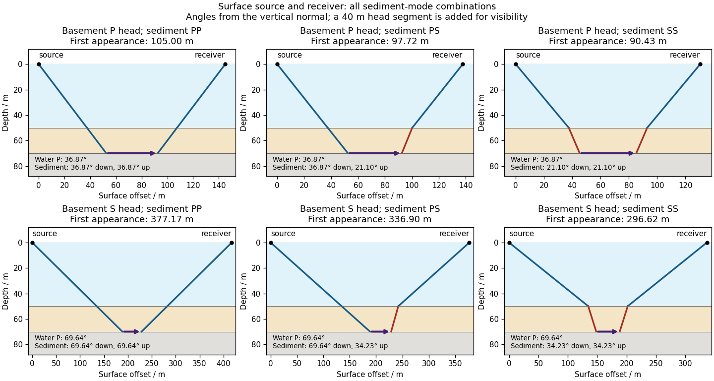

There is no separate finite-distance P head wave at the water–sediment interface: , so the nominal critical angle is , and a ray from a source 50 m above the interface cannot reach it at finite horizontal distance. Nor can the slower sediment S speed, , support a seismic head wave launched from water: it would require . A seismic reflection still exists at the seabed because the densities, hence the acoustic impedances, differ.
First appearance and first arrival differ. For each permitted branch the travel time isThe all-P basement P branch has . It overtakes the direct water P wave, , only at . The converted P-head branches have larger seismic intercept times, so even where they exist at shorter offsets they are later arrivals. The S-head branches are likewise later than the all-P P-head branch wherever they exist in this model. Reflections and layer reverberations can supply additional later phases.
Use a high-resolution multichannel seismic reflection survey, with closely spaced crossing lines or a suitable small three-dimensional survey over the turbine locations. It should map the seabed, the sediment–sandstone boundary, local faults, buried channels, and lateral changes relevant to foundations. Seismic reflection responds to acoustic impedance contrasts and can image an irregular boundary without requiring it to be a first-arrival refractor. Here even the seabed has a useful normal-incidence reflection coefficient of despite its zero P-velocity contrast.
A seismic refraction survey can provide complementary seismic velocities and geotechnical information, particularly using seabed multicomponent receivers for S waves. Its limitations as the principal imaging method here include the missing water–sediment P refractor, required offsets of hundreds of metres to obtain useful basement first arrivals, and weaker constraints on thin layers or velocity inversions. Variable bathymetry and sediment thickness further complicate simple refraction interpretations.
A shallow-towed boomer seismic source or small sparker seismic source is a sensible initial seismic source for penetrating about 20 m of sediment beneath a 50 m water column. A chirp sub-bottom profiler can add finer imaging of the upper cover where penetration permits; penetration depends on grain size, consolidation, gas, and seismic attenuation. A pilot line should establish the minimum useful source energy and bandwidth. Large low-frequency air-gun arrays are unnecessary for this shallow target. Small coastal vessels, sea state, tow stability and acoustic background constrain usable frequencies and operations. Marine mammals and other local receptors motivate a low-energy effective source, monitoring and appropriate operational mitigation.[ref]
High-resolution multichannel seismic system by United States Geological Survey. The institutional instrument description lists configurable boomer, sparker, hydrophone-streamer and complementary chirp equipment for shallow subsurface mapping.
The expected normal-incidence two-way travel times are for the seabed and for basement, separated by . Source duration, recording sample interval and bandwidth must distinguish them. As an initial vertical seismic resolution estimate, : gives about in the sediment, although usable resolution depends on the whole seismic wavelet and signal-to-noise ratio.
Choose shot and receiver spacing from the shortest useful wavelength, target size, maximum reflector dip, seismic migration needs and achievable navigation accuracy. For a plane event of horizontal seismic ray parameter , avoiding spatial aliasing requires approximately . Source spacing and receiver spacing also set midpoint coverage and seismic acquisition fold; adequate offsets enable moveout correction and velocity estimation. For nearly horizontal shallow reflectors a few-metre shot interval can be practical, whereas steep events at high frequency require denser spatial sampling. These values must be designed together rather than imposing one spacing for every target. Cross-line spacing must resolve lateral features between turbine sites, not merely along each track.
At a vessel speed of , one shot per second gives 2 m shot spacing and ample separation relative to a roughly target return, subject to the longer record needed for seismic multiples and source recovery. Shallow towing limits seismic source ghosts and receiver ghosts, but requires stable tow depth. Accurate positioning, tides, measured water sound speed, bathymetry and checks for seabed seismic multiples are essential for correct target depths.
Articles by others on the same topic
There are currently no matching articles.