Consider a stipulated series circuit containing an ideal resistor of electrical resistance and an ideal capacitor of capacitance . The same electric current passes through both. Their terminal electric potential differences add by Kirchhoff's voltage law, soA quick derivation uses : taking the derivative of the complex exponential multiplies the capacitor voltage phasor by , hence . Dimensionally, has units , matching .
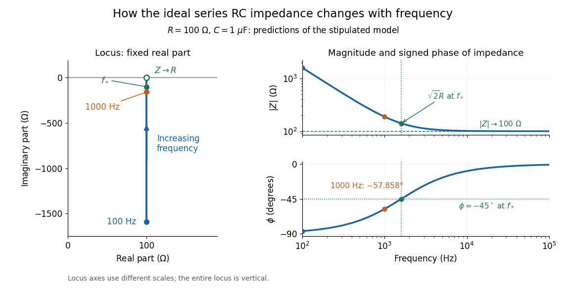
At frequency , the angular frequency is . The signed capacitive electrical reactance, modulus and complex argument of the total electrical impedance areApply across the complete series circuit. Its root mean square electric current isWith voltage as the zero-phase reference, the current phasor has complex argument : electric current leads. The phasor drops have moduli and ; these add as complex numbers, not as positive magnitudes. Their squared magnitudes sum to .

The mean absorbed power uses the root mean square values:The ideal capacitor has zero cycle-averaged absorbed power; all the mean absorbed power becomes Joule heating in the resistor.[ref]
University Physics Volume 2 by Samuel J. Ling and others. §15.4, equations 15.12–15.14 and the capacitor/inductor paragraph: RMS average power and zero ideal reactive average power
To see why the phase factor appears, average over a full cycle with and . The cosine addition formula reduces the average to ; the term at averages to zero. Independently, , and the capacitor energy returns to its starting value after each cycle.At fixed applied , the limit gives , and : the ideal capacitor blocks steady electric current. The limit gives , and . These are limits of the ideal lumped electrical circuit; unwanted lead inductance and component losses can invalidate that model at high frequency. At , the equal legs of the impedance right triangle give and without numerical evaluation. Measuring both the magnitude and the sign of the phase difference distinguishes this capacitor response from an equally large positive electrical reactance.
Articles by others on the same topic
There are currently no matching articles.