Tunneling through a controllable vacuum gap by Gerd Binnig and others made barrier width experimentally adjustable. Their apparatus used a pointed electrical conductor opposite a conducting plate, with fine positioning by piezoelectricity. Rubber-tube support and magnetic levitation above a cooled bowl exhibiting superconductivity suppressed vibrations; the junction itself remained near room temperature.[ref]
The readout was electrical resistance versus displacement at a fixed electric potential difference of 60 mV of either polarity. They observed an exponential function dependence spanning four orders of magnitude. Cleaning and better vacuum increased the inferred barrier from approximately 0.6-0.7 eV to 3.2 eV. Reproducible curves and the cleaning response argued against deforming contamination layers; an appropriate slope also helped exclude an ordinary conducting contact. The paper reports residual contamination, electronics-limited range and a jump attributed to release of thermal stress; its curve origins generally do not determine absolute gap widths.[ref]
Tunneling through a controllable vacuum gap by Gerd Binnig and others. p. 179, equation (1), Fig. 2 and accompanying control/limitation discussion
The ideal tunnel junction model explains the slope. At fixed small electric potential difference, fixed tip geometry and approximately unchanged density of states, take an effective barrier energy above the relevant electron states and approximate the current magnitude byThe coefficient includes the applied electric potential difference, available occupied and empty quantum states, and tip geometry. A single transmission probability is not an electric current: a junction combines contributions from many electron states in both directions, with the electric potential difference producing a net imbalance. Its tilted, material-dependent barrier is only approximated by the equal-exterior rectangular potential barrier; the exact single-particle formula above is not a complete junction model.
For the chosen model value electronvolts, . Increasing separation by multiplies by about , a reduction by about . The following diagram chooses solely for illustration; it contains no measured data and is not a fit to the 1982 curves.
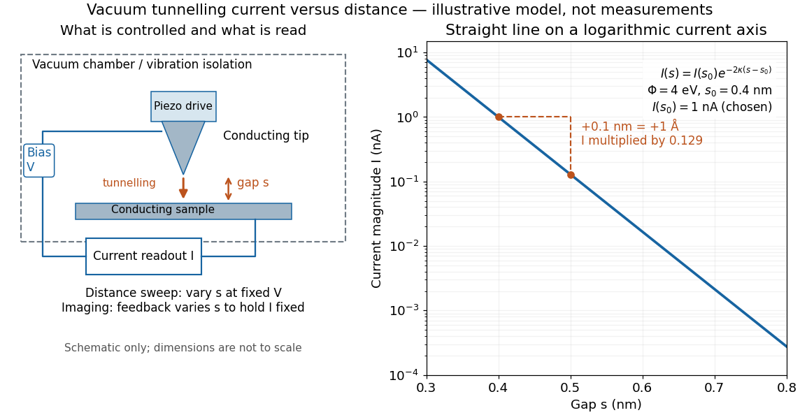

Distance calibration is essential. In Scanning Tunneling Microscopy: From Birth to Adolescence by Gerd Binnig and others, the authors describe an initial inferred barrier near 1 eV. Recalibration found only half the quoted piezo displacement sensitivity and raised the inferred barrier above 4 eV. Thus an exponential trace alone was insufficient evidence for tunnelling through vacuum. The model makes the sensitivity explicit: the inferred depends quadratically on the distance scale.[ref]
Scanning Tunneling Microscopy: From Birth to Adolescence by Gerd Binnig and others. p. 397, piezo-sensitivity calibration discussion
For scanning tunnelling microscopy, feedback control adjusts the vertical position to hold electric current fixed during a lateral scan; the recorded height follows separation only when the surface is electronically homogeneous. Changes in the local density of states can also change apparent height. This limitation is already explicit in the authors' account of constant-current imaging.[ref]
Scanning Tunneling Microscopy: From Birth to Adolescence by Gerd Binnig and others. p. 391, Fig. 2, joint local density of states; p. 396, Fig. 5(a), electronically homogeneous surface condition
The converse effect of piezoelectricity converts an applied electric potential difference into a small mechanical deformation, permitting fine control of a tunnel junction's separation.
A transducer using stress-induced electrical charge. A uniformly loaded slab of thickness has ideal open-circuit voltage sensitivity ; leakage and input capacitance change its measured response.
The change in output voltage per input stress under specified geometry, loading direction, frequency and electrical boundary conditions.
Linear electrical-displacement response to mechanical stress in a suitable piezoelectric material. It is distinct from the converse effect, in which an applied electric field causes strain. The measured voltage also depends on electrical loading and mechanical constraints.
For electrically isolated electrodes with unchanged free charge, the increment of normal electric displacement field is approximately zero. A constitutive relation such as then gives an induced field that balances stress-induced displacement. Finite leakage and input capacitance modify the voltage response.
A tensor coefficient relating an increment of electrical displacement to stress, or the corresponding converse strain response to electric field, under stated constitutive conventions. Charge-per-force units are equivalent to displacement-per-voltage units for the usual coefficients.
Dependence of piezoelectric displacement on the history and direction of the applied voltage. It differs from the continuing time-dependent relaxation called piezoelectric scanner creep.
Slow displacement relaxation following a change in piezoelectric scanner drive, even after the commanded voltage is held fixed. Settling and position-sensor closed-loop control reduce its effect on image coordinates.
Mechanical strain induced by an applied electric field. It complements the direct conversion of mechanical stress into electrical polarization.
A material exhibiting piezoelectricity, used in the Curie ionization-current measurement to supply a controlled electric charge.
Articles by others on the same topic
There are currently no matching articles.