A gyroscope is a rotating instrument whose rapidly spinning, nearly symmetric rotor provides a direction reference through its angular momentum. In an inertial frame, negligible external torque approximately preserves that direction by conservation of angular momentum. A transverse torque turns the angular momentum instead: the surprising sideways motion of a supported spinning wheel is precession. An ideal freely falling test gyroscope in general relativity has its spin undergo parallel transport along its timelike geodesic. Comparing that direction with distant reference axes measures Lense-Thirring precession; the direction need not remain fixed in arbitrary rotating coordinates.
A gyroscope direction reference is useful precisely because its direction can persist while its housing turns. A spinning-wheel precession experiment deliberately supplies gravitational torque to reveal how that persistence fails. The gyroscope vector geometry explains the direction, and slow steady gyroscope precession gives a numerical prediction with a check on its assumptions.
A flywheel's spin angular momentum must turn with the vehicle. The vehicle supplies torque to maintain this precession, and experiences the opposite reaction torque. With right-handed axes forward, left and up, a left turn has . A transverse flywheel with then produces body torque , opposing outward roll. Its magnitude is for turn radius . Reversing the flywheel reverses the effect.
A gyrocompass uses a spinning gyroscope and Earth's rotation to identify geographical north. In an ideal model whose axle is constrained to the local horizontal plane but free to turn about the vertical, the northward direction of the spin angular momentum is stable away from the poles; the opposite spin direction is unstable. A real settling instrument also requires damping. This is different from merely preserving an initial inertial orientation with a freely mounted gyroscope.
For a rapidly spinning gyrocompass with axle constrained horizontally, take azimuth positive from north towards west and positive spin angular momentum . In the terrestrial rotating reference frame, the vertical component of the torque equation, with zero external vertical torque, is . Here is the vertical moment of inertia and terms of order have been neglected. The small-angle approximation about gives simple harmonic motion with the displayed squared angular frequency. Linearizing about reverses its sign and gives an unstable equilibrium. At the poles this restoring effect vanishes. For a thin rotationally symmetric flywheel, the perpendicular axis theorem gives .
Choose a fixed support point and nonrotating axes in an inertial frame. All angular momenta, torques, and moments of inertia below refer to . Let point along the axle from toward the centre of mass, and let point vertically upward. Write for their angle. For a rapidly spinning symmetric top, the dominant angular momentum is , where is signed and is the axial principal moment of inertia. The sign of the axial angular velocity follows the right-hand rule.
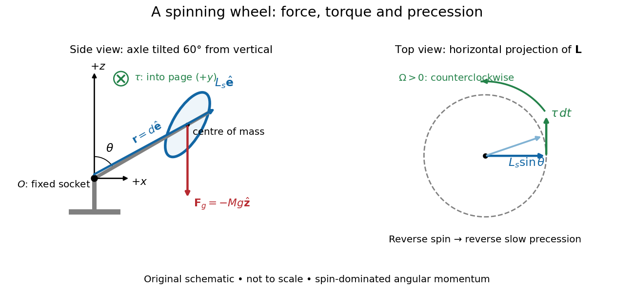
A fixed wheel support separates the downward gravitational force from the transverse torque and sideways precession
. Details. 
With mass , centre of mass distance , and constant gravitational acceleration , the gravitational force and its torque areAn ideal support applies a force at , so its lever arm and torque about vanish. At the instant the axle lies in the plane with a positive component, the gravitational torque points along . It adds toward , rather than along the downward force. The dot product identity shows why perpendicular torque changes direction without instantly changing magnitude. This vector balance and the slow-turning relation are developed in Chapter 20: Rotation in space (sections 20-2 and 20-3, equations 20.13–20.15).
For steady precession about the vertical, and . Equating the two cross products givesThe angular momentum tip traces a circle of radius : its sideways speed is . Both that radius and the gravitational lever arm contain , explaining its cancellation for . Exactly vertical alignment has zero gravitational torque and no distinguishable azimuthal precession to infer by this cancellation. Positive gives positive precession, counterclockwise viewed from above; reversing the spin reverses the slow precession. [ref]
11.4 Precession of a Gyroscope. University Physics Volume 1, section 11.4, equation 11.12 and the torque and precession-circle derivation
Purdue's Bicycle Wheel Gyroscope demonstration uses a bicycle wheel on a long axle, with a ball at one end seated in a freely rotating socket on a heavy stand. Spin the wheel by hand or with the supplied motor, seat the ball, and release the nearly horizontal axle. The readout is the axle sweeping around the vertical while the wheel continues spinning. Compare with the stopped wheel, which falls when one end is released; reverse the spin with the same support and the precession reverses. These are the page's documented apparatus, presentation, and reversal checks. [ref]
Bicycle Wheel Gyroscope by Purdue University, Department of Physics and Astronomy. 1Q-30, apparatus paragraph, Directions, and Suggestions for Presentation; page updated 30 November 2023
An alternative in Physics Demonstrations by Julien Clinton Sprott (section 1.3, Materials and Procedure) suspends one axle end by stainless steel wire and a fishing-line swivel. The swivel allows precession without winding up the suspension. Sprott describes the axle bobbing as nutation and precession becoming faster as spin decreases. A suspended support can move, whereas the calculation here assumes a fixed ; use the socket version for the closest realization. [ref]
Bicycle Wheel Gyroscope (section 1.3). section 1.3, Bicycle Wheel Gyroscope: Materials, Procedure, and Discussion
A proposed quantitative extension is to record an overhead view of an axle marker against a fixed angle scale, together with a side view for . Time successive overhead passages to estimate ; count passages of a rim mark to estimate . Record the spin sense too. Measure and the centre of mass offset of the whole moving assembly, and determine its axial moment of inertia independently. Wheel, axle, support, release angle, and observation interval should stay the same between spin trials. Measuring both and distinguishes azimuthal precession from nutation; an overhead movie alone can miss the latter. These camera readouts and parameter checks are proposed here, not reported measurements from the demonstration pages.
For slow precession, compare with , and test whether reversing reverses with nearly unchanged magnitude. A brief interval minimizes spin loss from friction; repeat at several starting spin rates rather than interpreting an entire slowing run as one steady state. A suspension restoring torque governed by its torsion constant, socket friction, support motion, a misplaced centre of mass, and a push at release can all supply extra torque or change the initial conditions. The swivel reduces the twist that activates the suspension's torsion constant; it does not demonstrate zero torque.
Steady precession keeps constant; nutation changes while the axle may also precess. Sudden release generally excites both. A small initial drop is consistent with conservation of energy and conserved vertical angular momentum: some gravitational potential energy supplies the motion around the vertical, and the axial contribution to vertical angular momentum adjusts. Bearing friction may damp the bobbing, but an ideal undamped heavy symmetric top need not settle into steady precession. Chapter 20: Rotation in space explicitly distinguishes uniform precession from release transients and nutation (section 20-3, paragraphs following equation 20.15).[ref]
Chapter 20: Rotation in space. section 20-3: sudden release, nutation, and the small drop needed for precessional angular momentum
Model the assembly as a heavy symmetric top with a fixed frictionless support, a uniform gravitational field, and centre of mass on its symmetry axis. Assume constant spin, negligible damping, and initial conditions prepared for uniform precession of a heavy symmetric top. Large spin means the transverse angular momentum from precession is small: . Also require . A large spin rate alone does not select steady motion after an arbitrary release.
For an original illustrative calculation, stipulateThe transverse principal moments of inertia are about the pivot, including the parallel axis theorem contribution. These inputs giveThe ratio is small; the more direct angular momentum ratio is small too. These are model calculations, not experimental results.
Check the approximation against the existing exact uniform precession of a heavy symmetric top condition. Its total angular momentum isAt constant , differentiating this expression and equating it to the gravitational torque givesFor the slow solution can be evaluated without subtracting two nearly equal numbers:It exceeds by about . The other solution is about and violates the assumed slow precession; the quadratic's two roots must not be conflated. Its discriminant must be nonnegative for these steady solutions to exist.
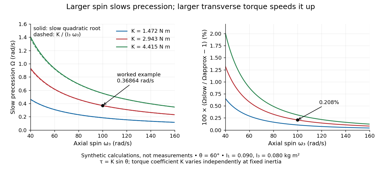
Synthetic steady-precession calculations: larger spin slows the drift and larger transverse torque speeds it up
. Details. 
The original curves hold fixed and vary spin and the imposed torque coefficient in . For gravity alone, ; the other curves are hypothetical changes in the transverse torque, not observations of this wheel. Solid curves use the slow quadratic root; dashed curves use . The second panel displays their relative difference. Increasing spin improves this approximation for the parameters shown. It does not remove nutation caused by inappropriate initial conditions.
Let a horizontal gyroscope have signed spin angular momentum along the axle. The disk's centre of mass is at and a counterweight is at . Gravity supplies torque . Since , steady horizontal precession gives the displayed signed vertical angular velocity. Neglect the axle's mass and the counterweight's axial spin moment of inertia. The zero-torque choice allows the axle to remain fixed. Moving the counterweight through this position reverses the gravitational torque and the associated slow precession.
For a rotor spinning about a principal axis with its support at the centre of mass, uniform gravity supplies no torque about that centre. With other external torques negligible, conservation of angular momentum preserves its direction in an inertial frame. A mount that permits free axis motion lets the housing rotate relative to that persistent direction, giving an orientation reference when external landmarks are unavailable. This is the useful limit opposite to the deliberately off-centre support in the spinning-wheel precession experiment. It supplies a direction, not a position or a full three-axis orientation from one axis alone.
For a small accumulated transverse torque about the centre of mass, the change in the direction unit vector is, to first order,Here is approximately constant over the short interval. Large angular momentum reduces drift for the same integrated transverse torque; parallel torque instead changes its magnitude. For , a constant transverse torque of over produces approximately , or , of direction change. This is another synthetic calculation. The persistent direction belongs to an inertial frame; its components can change in a rotating reference frame even with zero external torque.
Articles by others on the same topic
There are currently no matching articles.