Magnetic rigidity measures the resistance of a charged particle's momentum to bending by a magnetic field. The relativistic cyclotron orbit gives , where is the transverse gyroradius. For motion perpendicular to a uniform magnetic field, is the whole momentum. A measured magnetic rigidity fixes momentum per magnitude of electric charge; it does not by itself fix mass, kinetic energy, or the sign of the electric charge. This distinction makes the Anderson positron track experiment an especially revealing application of the Lorentz force.
The Anderson positron track experiment identified a light positively charged particle, now called the Positron, by combining magnetic bending, loss of kinetic energy in lead, and particle range. Each observation answered a different question: bending constrained momentum, the lead supplied a direction of travel, and particle range tested the proposed mass.
Carl David Anderson's The Positive Electron (1933), pp. 491–493, describes the 1932 discovery in a vertical cloud chamber with a magnetic field. A lead plate separated two photographed track segments. The effective viewing depth was along the magnetic field, with transverse diameter: this restricted out-of-plane motion. The photographic readout supplied curvature on both sides. Comparisons with Electron tracks under the same conditions constrained ionization; specific ionization was not directly measured for these events. He tested accidental alignment of unrelated tracks and rejected a reversed Electron interpretation requiring an increase of kinetic energy in lead. Assuming unit electric charge, the mass bound was about twenty Electron masses, rather than an exact mass determination. The paper credits Robert Andrews Millikan with the design and Seth Henry Neddermeyer with assistance.[ref]
The Positive Electron by Carl David Anderson. pp. 491–493, Fig. 1 and charge/mass discussion; p. 494, acknowledgment
Preparation used rapid piston expansion and a water–alcohol mixture in the cloud chamber; cooling permitted droplets to form along ionization trails. A camera photographed these droplets. Initially, expansions occurred at random, so many photographs contained no tracks. Later counter triggering improved the useful yield.[ref]
Carl David Anderson by William Hayward Pickering. Biographical Memoirs: Volume 73; William H. Pickering, Carl David Anderson, pp. 27–28: preparation, photographs and timing
In The Production and Properties of Positrons, his 1936 lecture, Carl David Anderson describes the chamber inside an electromagnet and explains why the lead plate was decisive: after losing kinetic energy, a particle bent more sharply. He describes a proton hypothesis predicting only of particle range, against an observed path longer than . These are historical values from the lecture, not the stipulated example below. The point was the incompatibility of particle range with the momentum inferred from curvature, rather than positive electric charge alone.[ref]
The Production and Properties of Positrons by Carl David Anderson. Nobel Lectures, Physics 1922–1941; pp. 365–366, electromagnet, lead-plate direction test and proton range comparison
A photograph records a path but supplies no arrow of time. The Lorentz force depends on : reversing both electric charge and direction of travel leaves the spatial bending compatible with the same path. Thus a particular arc can represent a Positron travelling one way or an Electron travelling the other. Knowing the magnetic field's polarity is necessary but insufficient. Gravity does not justify assuming that every cosmic ray track travels downward.
The lead plate adds a physical ordering. For a single particle crossing a passive absorber without an accelerating interaction, the outgoing momentum is smaller, so the outgoing gyroradius is smaller in the same magnetic field. The less curved segment comes first. Once this direction is assigned, the cross product in the Lorentz force determines the sign of electric charge. For the convention below, points out of the page; at upward velocity , . Bending to the right therefore means positive electric charge.
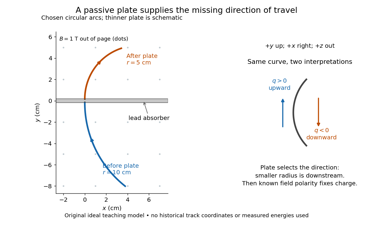

Magnetic forces do no work: the change of kinetic energy occurs through interaction with the material, not through the bending magnetic field. The ideal construction suppresses multiple scattering, kinetic energy fluctuations, and loss of kinetic energy in the gas. In an actual analysis one compares arcs away from the plate and allows a change of tangent from multiple scattering; one cannot interpret every kink as a change of electric charge. Short visible arcs, uncertain projection and small bending also limit a determination of magnetic rigidity.
For a concrete independent example, stipulate perpendicular motion, with the elementary charge, uniform magnetic field , incoming gyroradius and outgoing gyroradius . These are invented teaching inputs. Converting SI momentum to electronvolt units givesso and . Both a Positron and a proton with these momenta trace the same ideal arcs. Their kinetic energies differ because the relativistic energy-momentum relation givesThe second expression avoids subtracting nearly equal quantities when . For this calculation stipulate rounded rest energies and . The Positron interpretation gives and ; the proton interpretation gives only and . The corresponding proposed losses of kinetic energy are about and .
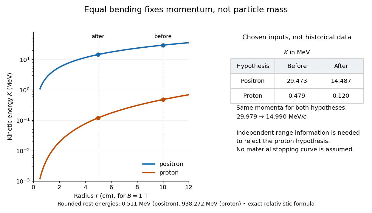

The small proton kinetic energy follows from , whereas here the Positron has and . Consequently magnetic bending alone cannot reject the proton. One needs an independent material constraint: could a proton at the proposed kinetic energy penetrate the plate and then travel at least the observed visible distance in the specified gas? A particle range shorter than that visible distance contradicts the hypothesis. The visible track need not include the stopping point: it already supplies a lower bound on particle range. No numerical particle range is assigned to this teaching example; that would require stopping data for the actual material and gas conditions. The experimental insight is to combine a geometric momentum measurement with an independent test of penetration.
Articles by others on the same topic
There are currently no matching articles.