At normal incidence the P wave and the two S wave polarizations decouple. In each uniform layer the relevant displacement satisfies , with for a longitudinal wave and for a shear wave. Its speed is and its seismic impedance is . A welded interface preserves particle velocity and traction. For displacement or velocity amplitudes, incidence from medium 0 onto medium 1 therefore givesReflection reverses the displacement sign when the receiving seismic impedance is larger. The energy-flux fractions areThe impedance factor matters: a displacement transmission coefficient larger than one does not imply energy amplification. Equal impedance eliminates reflection even when the densities and speeds differ.
For a stack, every interface creates reflected waves which can return to all earlier interfaces. A seismic layer transfer matrix incorporates those multiple reflections exactly. Use harmonic time dependence , particle velocity and compressive traction for a P-wave, or the negative relevant shear traction for an S-wave. Through layer of thickness ,This follows by solving and . Continuity means that the state passes unchanged across each welded interface. Put , with , and let the exterior impedances be . A unit incident velocity gives top state and bottom state . Eliminating these states yieldsFor real moduli and no attenuation, conservation of elastic-wave energy flux gives . Reciprocal incidence gives equal energy transmission in the reverse direction; flux-normalized amplitudes express that reciprocity without unequal exterior impedances obscuring it.
The wave phase accumulated in each layer determines constructive or destructive interference. For one layer between identical exterior media, an integral number of half-wavelengths makes and gives perfect transmission, regardless of the layer impedance. At quarter-wave phase thickness, a single matching layer with also gives zero reflection: the layer transforms the terminal impedance to . Away from these matching conditions there are transmission peaks, reflection maxima and rapid frequency-dependent phase changes. In the time domain these are a direct transmitted pulse followed by delayed internal reverberations and reflected echoes. Long residence in a resonant stack produces narrow peaks and long ringing, without creating energy.
For a periodic two-layer stack, the half-trace of one cell isThis is the periodic seismic multilayer stop band criterion. When the absolute right side exceeds one, the cell eigenvalues are a reciprocal growing/decaying pair and a long finite stack has exponentially small transmission. The missing transmitted energy is reflected, not absorbed. Large impedance contrast and repeated quarter-wave layers strengthen such stop bands. In pass bands the cell modes propagate, and a finite stack superposes transmission resonances on that propagation. An irregular stack need not have equally spaced peaks: the individual travel times and impedance contrasts set its interference pattern.
At sufficiently low frequency a finite stack has , so its leading reflection is that of the two exterior media alone. For many thin repeated layers with wavelength much longer than a cell, their effective density is the volume-weighted density and their normal modulus is the harmonic mean, . This follows by expanding each propagation matrix to first order and averaging its two coefficients. At high frequency, sharp interfaces still reflect: there is no general disappearance of reflection, only increasingly rapid interference fringes. Smooth impedance grading instead suppresses short-wavelength reflection when its variation scale is long compared with the wavelength.
These calculations provide a reproducible investigation: vary the layer travel times, impedances and number of cells; compute the matrix product; plot reflected/transmitted fluxes and check their sum. Adding attenuation makes the flux sum smaller than one and reduces reverberation peaks, while oblique incidence introduces Snell law for elastic waves and P-SV mode conversion absent from this one-dimensional setting. Impedance contrasts generate reflections, propagation phases organize their interference, and energy conservation separates reflection from genuine absorption.
Let be displacement along the source line and let be its force per unit length. The shear-horizontal wave equation isRotational symmetry about the line makes . Integrate over a disk of radius and use the divergence theorem:At a fixed regular time, a logarithmic singularity and its time derivatives are locally integrable; the inertial integral is and vanishes as . The leading balance is consequently , giving the SH line-source near-field singularityThe reference length only changes the bounded term; boundary conditions and source history determine that term. This is a local fixed-time statement, interpreted distributionally in time if the source force has jumps. It establishes logarithmic spatial dependence directly, without extrapolating far-field ray spreading into the source.
Away from the line source, insert a leading wavefront form into the shear-horizontal wave equation and match the two most singular orders. The first gives the eikonal equation . The next givesEquivalently, SH ray-tube amplitude transport conserves , where is the transverse width of a two-dimensional ray tube. A line source has straight radial elastic rays and for fixed angular width, soThe same geometrical spreading applies to the first nonzero derivative discontinuity or leading wavefront singularity; the source history determines which waveform and normalization occur. In three dimensions a point source instead has and amplitude proportional to .
This does not contradict the SH line-source near-field singularity. Ray transport describes an arrival-front limit with small, or the high-frequency field outside the immediate source neighborhood. The logarithm describes at fixed elapsed time and includes the tail behind the two-dimensional wavefront. For example, a causal step force has the exact radial displacementFor , this is , the near-source logarithm. For with , it isThe coefficient of the leading arrival singularity therefore has exactly the ray-theory dependence. A force impulse gives the corresponding leading field. The limits describe different regions of one causal solution; neither is a uniform approximation to the other.
Choose interface , source in medium 1 and transmitted medium 2 at . Write , take to be signed tangential slowness, and defineThe propagating range is ; the absolute value is needed if both azimuthal directions are included. Snell law for elastic waves preserves . The incident ray reaches the interface after time at horizontal position , withIn the transmitted medium its velocity is . Therefore the refraction of a cylindrical SH wavefront givesTime is measured from source emission. For a later emission add its time to the clock. These straight transmitted rays and their common-time endpoints determine the refracted wavefront; critical incidence and an evanescent transmitted field are excluded by the strict slowness bound.
At a welded interface, elastic-interface boundary conditions require continuous SH displacement and shear traction. Incident and reflected vertical slownesses have signs , givingThus the local displacement coefficient isIt multiplies the leading waveform discontinuity as well as a harmonic displacement. At the interface the incident amplitude from SH ray-tube amplitude transport is , where is the incident path length and is the source normalization from the previous part.
The transmitted geometrical spreading is not simply its total path length. Differentiate the ray position with respect to at fixed travel time and project onto the unit direction transverse to the transmitted ray, . Since , the transverse width per unit isThe derivative of contributes only in the ray direction and drops out of this projection. At entry,Within uniform medium 2 the leading amplitude varies as , so the required refraction of a cylindrical SH wavefront amplitude isThe local transmission coefficient and ray-tube spreading together incorporate both impedance contrast and refraction. Indeed the normal energy transmission fraction is , while the change of transverse width supplies the refraction factor in the conserved tube flux. If the media coincide, and , reducing this expression to as required. The formula holds for the stated propagating slownesses, without a critical or head-wave contribution.
Let the layer occupy , with a free surface at and rigid base at . Write an SH-wave as . The equation and boundary conditions giveThus and the guided SH modes between rigid and free planes haveThe propagating branch has and . Hence the rigid-base approximation to Love waves predictsAt each threshold and . As frequency rises, the phase velocity decreases towards and the group velocity increases towards . Frequencies below have imaginary horizontal wavenumber and do not give propagating guided modes. The infinite threshold phase speed does not violate causality: the limiting group speed is zero. These quarter-wave thresholds differ from the actual Love-wave cutoff frequencies of an elastic substrate.
The full Love wave problem replaces the rigid base by a decaying substrate displacement. With in the layer and below it,where and . Displacement continuity gives and traction continuity gives . The rigid base is therefore a good approximation only when : then the substrate displacement is small and lies close to .
Put , , , and . The complete dispersion branch can be parameterized without root finding:Then and . At the lower end, and . The Love-wave cutoff frequencies are , with zero cutoff for the fundamental. Thus the rigid-layer formula cannot describe the fundamental's low-frequency limit or the low-frequency part of an overtone: it would either give no propagating mode or predict , outside the trapping interval .
For comparable densities and a fixed mode index, . Write near the strong-dispersion transition. In the region controlling the group-velocity minimum of a high-contrast Love wave, and . The leading derivatives giveTheir minimum is atThe frequency estimate follows by inserting into : the two leading terms of size cancel. The real group velocity has a finite minimum and turns upwards near the rigid-layer threshold, whereas the rigid formula has zero group speed at its artificial threshold.
For a useful estimate of the validity range, put . The rigid prediction has . The finite-load phase correction is ; its changes to both and are small ifThe first condition keeps away from the substrate propagation boundary; the second controls the rapidly changing interface phase. Equivalently, the rigid formulas are reliable sufficiently above the actual group-velocity minimum, beyond its narrow transition interval. At fixed separated from one, they become asymptotically accurate as the contrast grows. They are particularly simple at , where both velocities approach . Within the transition and below it the full dispersion relation is required.
The small speed ratio alone is insufficient if the layer density grows so strongly that is not small. For such materials the exact load criterion and its frequency derivatives should be used; the preceding contrast estimates assume a bounded order-one density ratio and fixed .
With vertical shear modulus and horizontal shear modulus , force balance therefore gives the anisotropic shear-horizontal wave equationFor , the layer vertical wavenumber and substrate decay exponent areThe free top still gives ; the substrate still has . Welded displacement continuity and the now anisotropic traction continuity giveHence the anisotropic Love-wave dispersion relation isEquivalently, writing ,This replaces the isotropic speed in the layer equation by separate horizontal and vertical speeds and replaces the layer traction modulus by . No additional SH/P-SV coupling arises for the aligned symmetry axes and constitutive law here.
A rigid base still imposes , but nowThusThe vertical speed sets the resonance frequencies, while the horizontal speed sets the high-frequency limits and .
For the elastic substrate, put , , and . The exact parameterization isIt reproduces the isotropic analysis with replaced by in the frequency scale, by in the velocities, and by the two effective contrast parameters above. In particular the true cutoffs are , the group minima occur near , and a sufficient rigid-limit validity range isFor comparable horizontal and vertical layer speeds, a bounded density ratio and fixed mode index, the minimum estimate becomes and . If their ratio is extreme, that more specific minimum-depth estimate additionally needs ; the exact parameterization and load criterion remain valid without it. As in the isotropic case, neither a slow horizontal nor a slow vertical speed alone justifies the rigid boundary at cutoff or within the strong-dispersion transition.
Let denote the signed opening, positive when the faces separate, and let be the crack surface. Its displacement jump is . The singular strain associated with this jump has moment density . For the isotropic elastic stiffness tensor, contraction givesThe equivalent distributional body force is the negative divergence of this prescribed moment density:The resulting forced elastic wave in an isotropic solid equation is . This is a tensile-crack seismic source; it need not be represented as an ordinary smooth volume force. For a small nearly planar patch of area , uniform normal and opening , define its volume change . Its seismic moment tensor and point-source force areThe sign convention makes a positive opening a positive extensional moment. Reversing the convention for the displacement jump changes both signs together; the force is independent of reversing the orientation of the crack normal.
Complete the crack normal to an orthonormal basis with the first two vectors in the crack plane. The seismic moment tensor is diagonal in this basis:Each term gives an elastic force dipole, : two equal and opposite forces in direction , separated along , with moment . Hence there are two identical in-plane dipoles of strength and one normal dipole of strength . For positive opening and ordinary positive Lamé parameters, all are extensional and the normal one is larger by .
More generally, stable isotropic linear elasticity requires and . These imply , so the normal dipole has greater magnitude even if an auxetic material has negative and compressive in-plane dipoles. The point source has zero net force, because it differentiates a delta function, and zero net torque, because its moment tensor is symmetric. Its normal moment distinguishes opening from a pure shear dislocation.
Treat a small patch as the point tensile-crack seismic source at , with and . Let , , , and . Source convolution and an integration by parts give the point-moment elastodynamic displacementThe derivatives act on angular factors and on retarded times as well as on powers of ; keeping only the explicit Green-function terms would miss the static displacement.
Set , andConvolving the elastodynamic Green tensor with the opening history givesUse , , , andFor example, , while differentiating the near-field angular tensor gives . Combining these with the endpoint terms in yieldsFor the normal crack, , , and . Explicitly, the three nonradiative vector coefficients in the last two lines areThus those lines are . The small-source approximation assumes the patch size is small relative to both and the wavelengths of interest; a finite crack is obtained by integrating the same point-patch expression over its surface with its local opening and normal.
The first two terms are the radiative P wave and S wave displacements:They decay as and are purely transient: once the opening rate vanishes, each disappears after its respective arrival time. The P displacement is longitudinal and the S displacement transverse. An abrupt opening history makes these formulas distributions; a smooth finite-duration intrusion gives ordinary pulses.
Suppose the source starts from zero opening and ends with volume change . At times later than the end of intrusion plus , both retarded openings equal andThe remaining terms combine to the static displacement fieldIt decays as , so it must not be identified with the transient far-field pulses.
For a Poisson solid, , and . Let be polar angle from the crack normal, with unit vector in the increasing- direction. Then and . The tensile-crack radiation pattern becomesAt fixed and positive opening rate, the P pattern is outward, has no angular node, and is three times larger along the normal than in the crack plane. The signed S amplitude has four alternating lobes: it vanishes along the normal and in the crack plane, and its magnitude is maximal at to them. Neither field has an azimuthal SH component about the crack normal.
The final static field simplifies toIts radial part is outward near the poles, changes sign at , and is inward in the crack plane. The tangential part has the same signed angular factor as the S radiation, but is permanent and has a different distance dependence. Its radial sign changes are not nodes of the whole vector because the tangential component generally remains nonzero there. Rotating a meridional sketch around the crack normal gives the complete three-dimensional axisymmetric pattern.
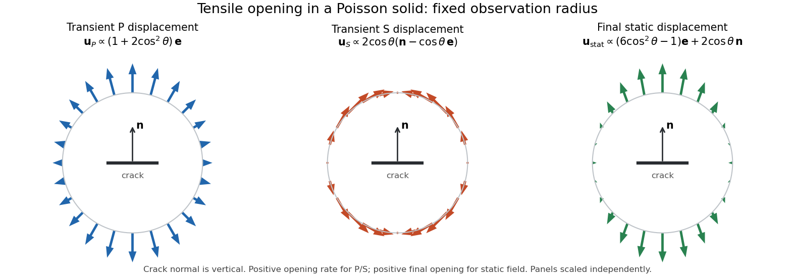
Transient P and S displacement patterns and final static displacement for a tensile crack in a Poisson solid
. Details. 
Articles by others on the same topic
There are currently no matching articles.