A wavefront connects points with the same wave phase at one specified time. It is a surface, rather than the trajectory of a particular piece of light. For a scalar monochromatic wave written as , a wavefront is a connected level set of the phase function ; different surfaces can share the same wave phase modulo . A plane wave has planar wavefronts. An outward wave from an ideal point source in a uniform medium has spheres as wavefronts, while an optical lens can turn nearly planar wavefronts into converging ones. The wavefront describes wave phase, not wave amplitude: drawing it does not say how bright the beam is. [ref]
The relation to light rays becomes precise in a stationary medium with isotropy, negligible loss and a real positive scalar refractive index . In the geometrical optics limit, spatial changes in the refractive index and wave amplitude are slow on the local wavelength scale. For a single smooth propagation branch, writeHere is the angular frequency, is the vacuum speed of light, has units of length, and the last relation is the optical eikonal equation. The local wavevector is . Its direction is normal to a smooth wavefront, since a gradient is normal to its level sets. A forward light ray has unit tangent vector , so it follows this normal under the stated assumptions. Along that light ray, : the change in is the optical path length. This is the short geometric argument linking wavefronts, light rays and optical path length. [ref]
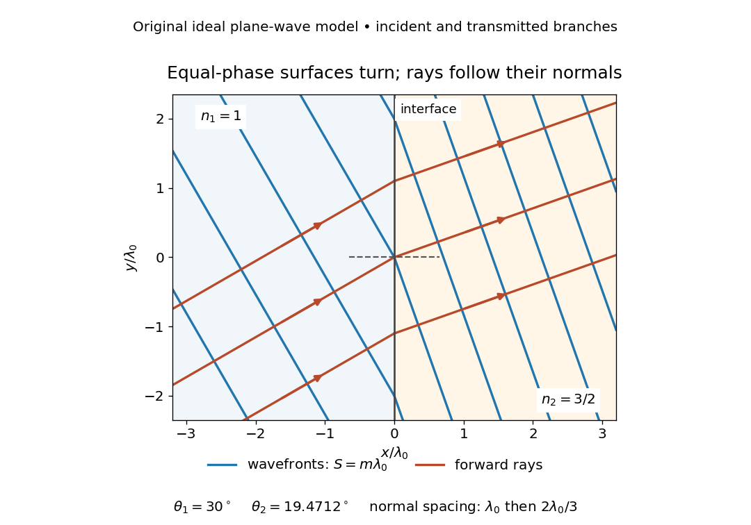

The diagram shows incident and transmitted branches separately, with the reflected branch omitted. Its stipulated refractive indices are and , and its incident angle is to the interface normal. At a stationary interface, the frequency and tangential wavevector agree on the two sides: Snell's law gives , hence . The wavefronts turn while their normal spacing decreases from to , where is the vacuum wavelength. More explicitly, with normal to the interface and tangential, take for and for . These functions agree at ; the drawn wavefronts are at with . This is an exact piecewise plane wave phase construction for the stipulated transparent media, not measured material data. [ref]
The normal-to-wavefront rule requires its assumptions. In a medium with anisotropy, the wavevector remains normal to a smooth wavefront, but the group velocity and energy flux need not follow it. [ref] Near a wave caustic, where multiple light rays meet, one smooth phase function may no longer describe the field; diffraction and the full wave amplitude matter. A wavefront is also not generally a surface of equal pulse arrival time. In a medium with optical dispersion, a monochromatic wave phase moves with the phase velocity, while a sufficiently narrow wave packet follows the group velocity. Even identical optical path lengths at one frequency can give different group delays. The usual equal-travel-time picture needs a common launch reference and a nondispersive ray model; an arbitrary broadband disturbance has no single monochromatic wavefront.[ref]
An optical path length measures how much propagation wave phase a path accumulates, expressed as the distance that would accumulate the same wave phase in vacuum. A centimetre in a uniform medium with refractive index has optical path length , although its geometric length remains . This makes optical path length useful whenever two contributions must arrive with matching wave phases, from an optical lens to a Michelson interferometer. [ref]
For a specified path at fixed angular frequency , the optical path length is the line integralHere is geometric arc length, and is the phase refractive index, evaluated at the same frequency everywhere. The propagation interpretation assumes a stationary linear medium with isotropy, a real positive scalar refractive index and negligible loss, on a valid geometrical optics branch. The path can curve; at sharp interfaces apply the appropriate matching conditions to each segment. A prescribed curve has a mathematical line integral, but it predicts a propagation wave phase only when it represents the physical branch. [ref] Optical fibers can require a mode wavenumber rather than the bulk refractive index along a guessed light ray. [ref]
Fix the vacuum wavelength , with frequency and vacuum wavenumber . In a locally uniform medium the wavelength is , while the frequency stays unchanged at a stationary interface. With the convention , propagation from a specified starting wave phase contributesThe relative reference includes launch wave phases and any extra wave phase from mirrors, beam splitters or coatings. Thus is a propagation contribution, not an absolute detector wave phase independent of the apparatus. If the reference contributions stay fixed, a change in optical path difference changes the phase difference by . Using the material wavelength again in this formula would count the refractive index twice. [ref]
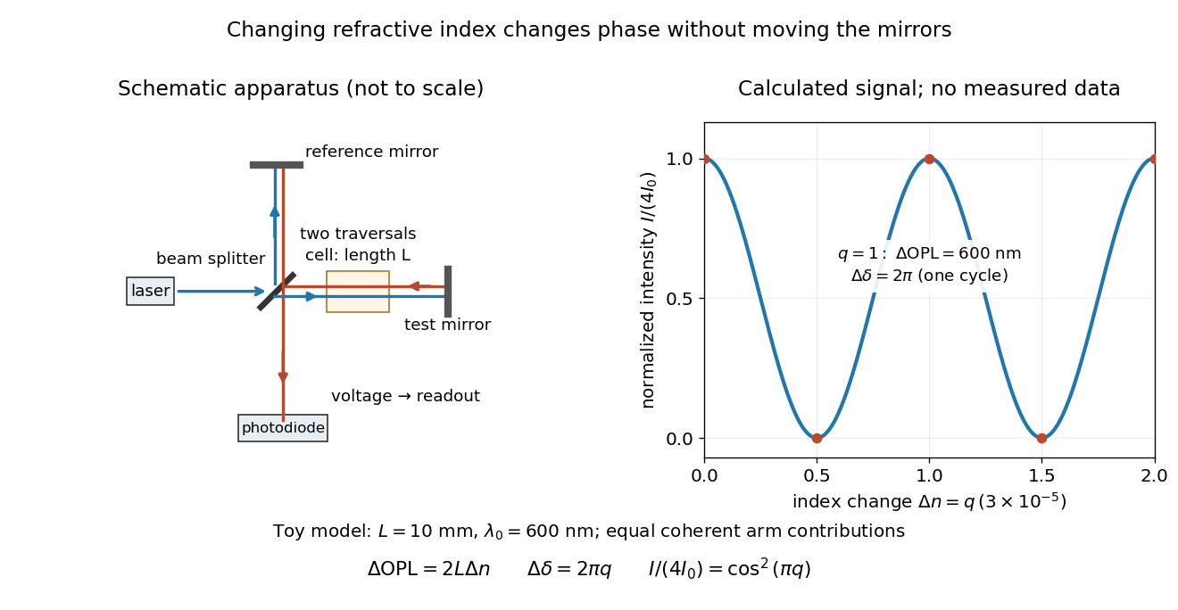
Optical path difference in a Michelson interferometer: apparatus schematic and a calculated phase difference readout
. Details. 
A motivating measurement turns invisible optical oscillations into a slowly changing electrical signal. MIT's teaching experiment uses a laser, a beam splitter, two returning mirrors, an amplified photodiode, an oscilloscope and a calibrated mirror actuator driven by a function generator. The returning beams overlap on the photodiode; one channel records detector voltage and another the actuator drive. The measured observable is the changing light intensity, including its maxima and minima, rather than direct timing of an optical cycle. A calibrated displacement per drive voltage and the spacing of the extrema relate geometric motion to the phase difference. The guide infers the laser wavelength from known actuator calibration; conversely, with independently known vacuum wavelength and ambient refractive index, the same relation calibrates mirror motion. These two unknowns cannot both be inferred from fringe spacing alone. [ref]
For a proposed change-of-medium measurement, keep the mirrors fixed and put a transparent cell of internal length in one arm. Compare its contents at refractive indices and , leaving its windows in place. At normal incidence the two traversals giveHere is the signed number of whole interference fringe cycles plus any resolved fractional cycle, counted continuously. A mirror displacement instead gives ; distinguish this double-pass factor from a single pass in a Mach-Zehnder interferometer. OpenStax's gas-cell worked example provides the same double-pass reasoning; it is a teaching calculation rather than a published measurement dataset.[ref]
An exact toy calculation makes the sensitivity visible. Stipulate , and . Then and : a full interference fringe cycle, despite unchanged geometric lengths. For a continuous change , let and choose the initial detector phase difference to be zero. Equal coherent detected arm contributions of light intensity predictThe plot is this stipulated model: gives a minimum, restores a maximum, and the reference level is chosen by adjustment of the apparatus. It contains no measured values or assigned properties of a real gas. The equivalent mirror travel in vacuum is per cycle. A single endpoint light intensity cannot distinguish from ; the continuous fringe count carries the missing information.
For an interpretable cell measurement, establish the initial phase difference with a small calibrated mirror scan, then track slow changes through successive interference fringes. Measure the dark signal and each arm separately, keep photodiode gain within its linear range, align both beams on the same region and match their linear polarizations. Monitor interferometric visibility and keep arm delays within the useful optical coherence time. Record cell length, contents, pressure and temperature; return to the starting condition to check drift. Changes in window deformation, cell length, external air or mirror position also change optical path length, so a reference cell or an independently monitored mechanical path is needed to isolate the contents' refractive index. These controls are deductions from the model, not a claim that the illustrated apparatus was operated. Loss of fringe count leaves a whole-cycle ambiguity; at an intensity extremum the first derivative with respect to phase difference vanishes, so a scan around phase quadrature is more sensitive to small changes. Broadband illumination, unstable optical coherence, vibration and strong loss can invalidate a simple one-frequency inference.
An optical path difference subtracts two optical path lengths at the same frequency and with specified endpoints and sign. Its phase difference contribution is , in addition to any apparatus reference wave phase. For wavefront error, the comparison is usually between an actual wavefront and an ideal reference wavefront.
In a monochromatic two-path interferometer, an ideal phase plate of thickness and refractive index adds phase at normal incidence. The interference pattern is unchanged when for integer , provided transmitted amplitudes and alignment are unchanged. Calling the smallest index requires specifying the admissible range; excludes the optically null solution.
The group refractive index is for a transparent isotropic propagation branch with forward group velocity . Differentiating the local wavenumber givesThe last formula gives the propagation group delay along a path whose geometry is fixed as frequency varies; additional apparatus wave phases require their own frequency derivatives. For a narrow wave packet with little loss and negligible reshaping, it approximates the transit of its wave envelope. In the nondispersive case , it reduces to . An optical path length at one frequency contains no information about , so in a medium with optical dispersion it cannot by itself determine the group delay. [ref]
For an original local model near , choose two equal geometric paths of length , with and . At both optical path lengths equal , and matched launch and interface references give equal carrier wave phases. But and , so their group delays differ by . This local stipulated model is a counterexample to identifying equal wave phase with equal pulse arrival; it asserts no material response outside the narrow band considered. Strong loss or pulse reshaping requires a fuller propagation model, and group delay need not time the earliest causal response.
For vacuum incidence at fixed angle into a transparent isotropic medium, Snell's law gives . Thus , andAngles must be differentiated in radians. This determines the local group velocity from a first derivative of measured refraction angles; pulse broadening needs further information about group velocity dispersion and absorption.
The group delay is the frequency derivative of an unwrapped transfer wave phase, using the convention. It predicts the leading delay of a narrow wave envelope when the transfer wave amplitude and the delay vary little across its band; it is not generally a signal-front arrival time.
The second derivative of spectral phase with respect to angular frequency; it measures variation of group delay with angular frequency.
The cubic term in a component's spectral phase, conventionally written , where is an angular frequency offset.
A wavefront error is the difference in optical path length from a reference wavefront, often an ideal plane or sphere. Its root mean square should specify the illuminated pupil and which modes, such as constant phase or image displacement, have been removed.
For a real wavefront error , its squared spatial root mean square is . Orthogonal unit-peak sine modes have mean square , so , whereas the coefficient norm is . On a finite optical pupil orthogonality needs checking; independent uniform random wave phases give the same diagonal after wave phase averaging. This normalization matters when a speckle contrast of a sinusoidal wavefront error is specified by peak wave amplitude.
Articles by others on the same topic
There are currently no matching articles.