Use phasors with time dependence . The electrical impedance is the complex number relating the sinusoidal voltage and electric current: is their amplitude ratio and is the voltage phase relative to the electric current. The component laws giveThus the resistor has zero relative phase, the capacitor voltage lags its electric current by , and the inductor voltage leads its electric current by . The ideal capacitor and inductor store and return energy; the real electrical impedance of the resistor describes dissipation.
The original diagram's upper arm is a series resistor and capacitor; its lower arm is a parallel resistor and capacitor. The output is the upper-minus-lower voltage across that parallel arm. Assume an ideal input voltage source and an unloaded output. Their electrical impedances areFor this series-parallel RC band-pass filter, the voltage divider gives, with ,Taking the real part of yields the steady outputInitial charging contributes decaying transients if the source is switched on at a finite time; the displayed expression is the sinusoidal steady state. The output polarity matters: reversing the indicated output voltage would multiply by .
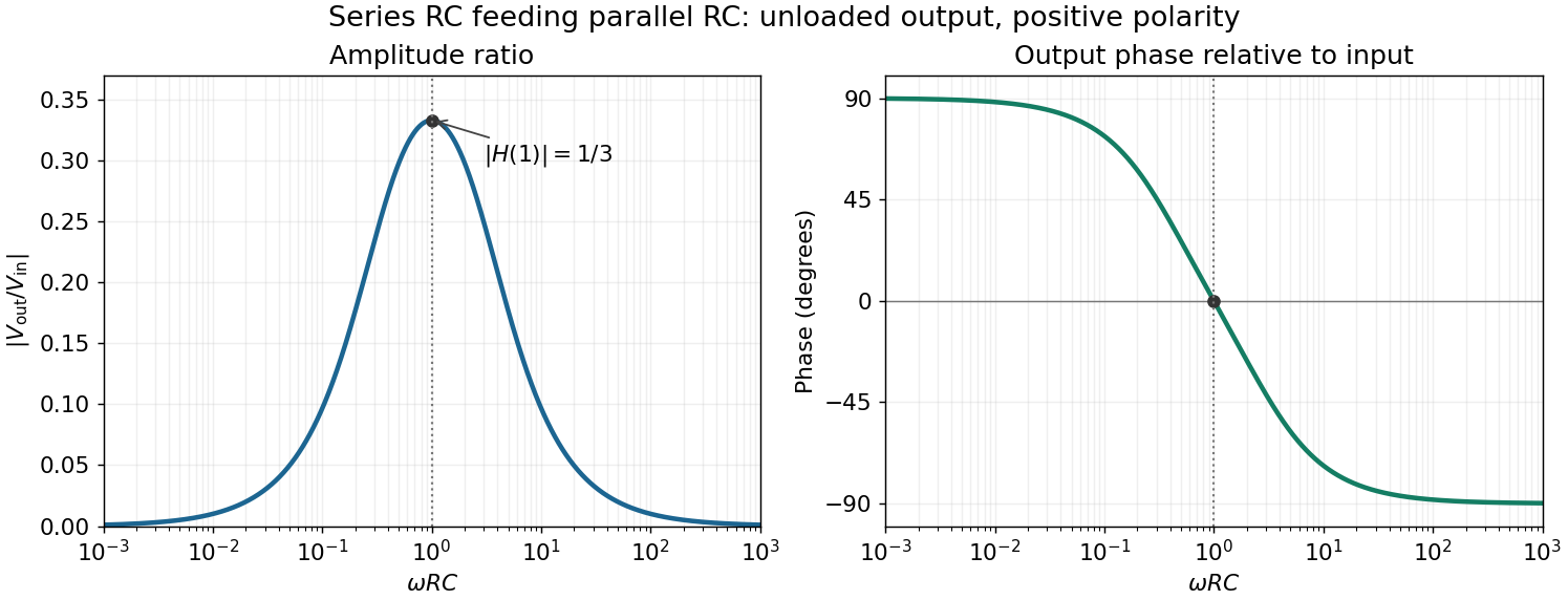
For positive angular frequency, the squared amplitude response of the series-parallel RC band-pass filter isIts denominator is minimized exactly when , soThis is a band-pass filter maximum produced entirely by the two RC arms; the drawn electrical circuit contains no inductor. The low- and high-frequency limits areThus the output amplitude tends to zero linearly with at low frequency and as at high frequency. In real time,The upper series capacitor suppresses low frequencies, while the lower shunt capacitor suppresses high frequencies.
In the chosen phasor convention, output phase minus input phase isThe real part of the denominator is positive, so this principal arctangent is continuous throughout the positive-frequency range. Below , the output leads the input, approaching at low frequency. Above , it lags, approaching at high frequency. At the maximum,The input and output are in phase there, with the positive one-third voltage ratio found above.

Articles by others on the same topic
There are currently no matching articles.