At direct current an ideal capacitor is an open circuit. A finite measured electrical resistance therefore requires the resistor and capacitor to form a parallel circuit, with . Use phasors proportional to . The electrical admittance and complex impedance areInterpreting the stated AC value as the measured impedance magnitude, and give . ThusThe electric current leads the applied voltage by . Strictly, AC “resistance” is ambiguous: if it means , the same parallel circuit instead gives , , and . A measurement of selects the boxed interpretation.
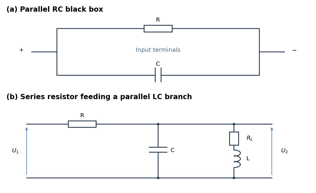
Parallel RC network and resonant voltage divider
. Details. 
A suitable electrical circuit has in series with the input and a shunt branch consisting of in parallel with the lossy inductor ; take the output voltage across that shunt branch. This is the middle arrangement in the circuit figure. In terms of its complex impedance,At direct current the capacitor is an open circuit and the inductor contributes only , so . ThereforeWhen is neglected, . At the antiresonance its electrical admittance vanishes, so reaches its maximum value of one. ConsequentlyThis value uses precisely the requested lossless approximation; keeping changes both the peak position and its height. A transfer function peak and one DC measurement do not uniquely identify every possible two-port network, but the displayed arrangement meets both observations to the stipulated approximation. Also, the angle brackets in the source must denote AC wave amplitudes or root mean square values: the literal time averages of sinusoidal voltages are zero, whose ratio would be undefined.
Articles by others on the same topic
There are currently no matching articles.