After asserting and releasing the active-low Start pulse, a valid sequence is , then , then , with each input held high through the relevant sampling interval. The first JK flip-flop has and is clocked by , so the rising clock edge of samples and sets . Once that output has settled, a rising clock edge of clocks the second JK flip-flop with , setting .
The essential conditions concern sampled levels: must be high at a rising clock edge of , and must then be high at a rising clock edge of . Separate edges with adequate setup and hold time avoid an ambiguous simultaneous transition.
The initial input levels do not initialize the stored bits. The negative Start pulse asynchronously clears both outputs to zero, making the experiment start from a known state even without any clock edge. Once Start is released, the circuit can recognize a fresh sequence. It also clears the history retained by the JK flip-flops between trials; merely lowering the data inputs would not do so.
With , a JK flip-flop obeys at its positive clock edge: holds its old state and sets it. Thus each original stage is a sticky record of a previously sampled high input until Start clears it. A D flip-flop instead obeys , so a later sample of zero can clear the output.
Connect each replacement D input where the corresponding J input was connected, preserving the clocks and asynchronous clear. The first valid sequence after Start still sets both outputs. Afterwards, let fall and apply another rising clock edge to . The D version clears ; the JK version retains . A subsequent rising clock edge of can therefore clear only in the D version. Neither circuit continuously tracks its data input between clock edges.
Each stage has and therefore toggles. The printed clock symbols have no inversion bubble, so they are positive-edge triggered; each later clock is driven by the previous uncomplemented output. Consequently the circuit is a ripple counter that counts down modulo eight. A zero least significant bit rises to one and propagates the transition; a one falls to zero and stops it. For example, the settled transition from is , whereas is followed by .
After input pulses the settled value is , givingThe answers are , , and , respectively, in most-significant-first order. Treating these as falling-edge stages would reverse the counting direction and would not follow the drawn clock symbols.
The inclusive range contains distinct states. An -bit binary counter has states, so 31 JK flip-flops in total are necessary and sufficient for the required capacity: add 28 to the three shown.
This is a capacity calculation. The printed positive-edge, uncomplemented-output cascade visits these codes in descending order. To obtain increasing numerical order one must change the cascade clock polarity, for example clocking each positive-edge stage from the preceding complemented output.
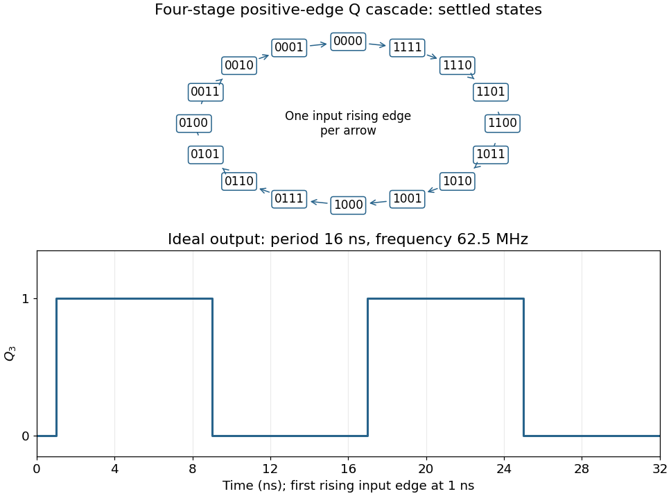
Connect the fourth JK flip-flop with and clock it from , retaining the source's positive-edge convention. Read the four-bit state as . Its state-transition diagram is a single cyclewith one input rising clock edge per arrow; the figure displays every state explicitly.
Each stage halves the preceding triggering frequency. is an ideal square wave with a 50-percent duty cycle at , with wave period and high and low intervals of . Its initial phase depends on the starting state. The figure chooses initial state and a first input rising clock edge at . Actual ripple propagation shifts edge times and creates intermediate transient codes; no device delays were supplied, so the waveform describes settled ideal logic.

Articles by others on the same topic
There are currently no matching articles.