Source paper: released examination archive. The dated cover identifies the 17 June 2021 preliminary examination, A10101W1. All printed alternatives are treated below.
After asserting and releasing the active-low Start pulse, a valid sequence is , then , then , with each input held high through the relevant sampling interval. The first JK flip-flop has and is clocked by , so the rising clock edge of samples and sets . Once that output has settled, a rising clock edge of clocks the second JK flip-flop with , setting .
The essential conditions concern sampled levels: must be high at a rising clock edge of , and must then be high at a rising clock edge of . Separate edges with adequate setup and hold time avoid an ambiguous simultaneous transition.
The initial input levels do not initialize the stored bits. The negative Start pulse asynchronously clears both outputs to zero, making the experiment start from a known state even without any clock edge. Once Start is released, the circuit can recognize a fresh sequence. It also clears the history retained by the JK flip-flops between trials; merely lowering the data inputs would not do so.
With , a JK flip-flop obeys at its positive clock edge: holds its old state and sets it. Thus each original stage is a sticky record of a previously sampled high input until Start clears it. A D flip-flop instead obeys , so a later sample of zero can clear the output.
Connect each replacement D input where the corresponding J input was connected, preserving the clocks and asynchronous clear. The first valid sequence after Start still sets both outputs. Afterwards, let fall and apply another rising clock edge to . The D version clears ; the JK version retains . A subsequent rising clock edge of can therefore clear only in the D version. Neither circuit continuously tracks its data input between clock edges.
Each stage has and therefore toggles. The printed clock symbols have no inversion bubble, so they are positive-edge triggered; each later clock is driven by the previous uncomplemented output. Consequently the circuit is a ripple counter that counts down modulo eight. A zero least significant bit rises to one and propagates the transition; a one falls to zero and stops it. For example, the settled transition from is , whereas is followed by .
After input pulses the settled value is , givingThe answers are , , and , respectively, in most-significant-first order. Treating these as falling-edge stages would reverse the counting direction and would not follow the drawn clock symbols.
The inclusive range contains distinct states. An -bit binary counter has states, so 31 JK flip-flops in total are necessary and sufficient for the required capacity: add 28 to the three shown.
This is a capacity calculation. The printed positive-edge, uncomplemented-output cascade visits these codes in descending order. To obtain increasing numerical order one must change the cascade clock polarity, for example clocking each positive-edge stage from the preceding complemented output.
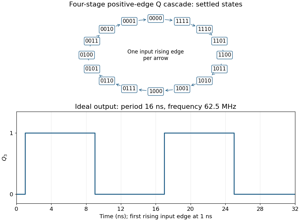
Connect the fourth JK flip-flop with and clock it from , retaining the source's positive-edge convention. Read the four-bit state as . Its state-transition diagram is a single cyclewith one input rising clock edge per arrow; the figure displays every state explicitly.
Each stage halves the preceding triggering frequency. is an ideal square wave with a 50-percent duty cycle at , with wave period and high and low intervals of . Its initial phase depends on the starting state. The figure chooses initial state and a first input rising clock edge at . Actual ripple propagation shifts edge times and creates intermediate transient codes; no device delays were supplied, so the waveform describes settled ideal logic.
The shifts multiply the original array indices by four, and the following additions form byte memory addresses. The load into
$s0 changes the variable itself, but the address of the next element of A has already been saved. The complete effect isi = x
x = A[i]
B[y] = x + A[i + 1]Here
i is a fresh temporary. Both the assignment to and the assignment to matter. Writing only would omit the observable change to . The interpretation assumes four-byte array elements, valid aligned addresses, and arithmetic within range; the source uses trapping signed additions. The address of is computed before changes.Use the conventional integer calling convention:
$a0 holds the argument and $v0 holds the result. The function is recursive, so every call must preserve its own return address and original argument. The first recursive result must also survive the second call; a caller-saved register alone would not protect it.This implementation reserves a 32-byte stack frame, keeping the stack pointer eight-byte aligned. Offsets 0–15 are available as the outgoing argument area, 16 stores the original argument, 20 stores the first result, 24 is padding, and 28 stores the return address. It changes no callee-saved register. Assemble in classic MIPS delayed-branch mode with instruction reordering disabled, such as
.set noreorder.foo:
addiu $sp,$sp,-32 # allocate 32-byte aligned frame
sw $ra,28($sp) # save caller return address
sw $a0,16($sp) # save original n
beq $a0,$zero,foo_base
sll $zero,$zero,0
addiu $t0,$zero,1
beq $a0,$t0,foo_base
sll $zero,$zero,0
addiu $t0,$zero,2
beq $a0,$t0,foo_base
sll $zero,$zero,0
addiu $a0,$a0,-1
jal foo
sll $zero,$zero,0
sw $v0,20($sp) # preserve foo(n-1) across next call
lw $a0,16($sp) # recover original n
sll $zero,$zero,0
addiu $a0,$a0,-3
jal foo
sll $zero,$zero,0
lw $t0,20($sp)
sll $zero,$zero,0
addu $v0,$v0,$t0 # combine the two recursive results
beq $zero,$zero,foo_return
sll $zero,$zero,0
foo_base:
addu $v0,$a0,$zero # base case result is n
foo_return:
lw $ra,28($sp)
sll $zero,$zero,0
addiu $sp,$sp,32 # release the frame
jr $ra
sll $zero,$zero,0All displayed operation mnemonics denote single machine instructions. In particular,
sll $zero,$zero,0 is the actual harmless shift encoding often abbreviated by the pseudoinstruction nop; addu $v0,$a0,$zero performs a copy without the move pseudoinstruction. Each branch or jump has an explicit harmless branch delay slot, and harmless shifts also separate loads from their subsequent uses. The base cases return the original argument; other calls return the sum of the two recursive values. Every return restores the saved return address and exactly undoes the stack allocation.[ref]MIPS32 Architecture For Programmers Volume II by MIPS Technologies. Revision 2.00, ADDIU and ADDU, pp. 37–38; JAL and JR, pp. 139 and 144
The stated domain is nonnegative integer , with sufficient stack space and a result representable in the intended integer type. The non-trapping additions implement that mathematical result within range; beyond it, machine wraparound would require a separately specified integer semantics.
A register file with 256 entries needs bits per register index. Under the intended assumption that eight times as many instructions are obtained by expanding the primary opcode field, its width grows from six to bits. Thus opcode: 9 bits; rs, rt and rd: 8 bits each.
These four fields alone require bits, already exceeding a 32-bit instruction encoding. Retaining the five-bit shift amount and six-bit function field of a MIPS R-type instruction gives 44 bits. The processor's data word need not become wider merely because it has more registers.
The opcode conclusion is conditional: MIPS also uses secondary function fields, so an eightfold increase in the number of semantic operations does not by itself force a nine-bit primary opcode. That is the straightforward field-expansion interpretation of this exercise.
On the same primary-opcode expansion interpretation, opcode: 9 bits; each register field: 8 bits. The printed
rd is a naming slip: a conventional MIPS I-type instruction has fields rs and rt, with the latter sometimes serving as the destination. There is no separate rd field.Keeping the original 16-bit immediate requires bits per instruction. If the instruction encoding were held at 32 bits, only seven bits would remain for the immediate, reducing immediate arithmetic and addressing ranges. A uniform encoding for both enlarged formats would have to accommodate the longer R-type case too; any padding or revised format policy must be specified separately. Register count and instruction width do not determine data-word width.
More processor registers can reduce register spills and the associated loads and stores. A richer instruction set may also replace several old machine instructions by one new operation. Both effects can decrease the number of instructions in a compiled program, although a particular program might obtain no benefit.
Wider instruction encodings increase the bytes per instruction. Consequently the total machine-code size can increase or decrease: approximately, it is instruction count times average encoded instruction width, with alignment and padding also relevant. There is no universal net direction without the program and revised encoding. The length of assembly language source text is a separate matter and is not determined by instruction bit widths.
Compute the two complements with the two NOT gates, then form and with the two AND gates. Feed those outputs to the OR gate:Exactly one product is one when the inputs differ; both products are zero when the inputs agree. This uses precisely the allowed two inverters, two two-input AND gates and one two-input OR gate.
Every AND gate and OR gate is a monotone Boolean function: changing an input from zero to one while leaving all other inputs unchanged cannot change the output from one to zero. By structural induction over a Boolean circuit, a composition of these gates is also a monotone Boolean function. Constant inputs do not alter that conclusion.
Logical negation cannot be implemented, since it sends to and to , violating the defining order property. Hence these two gate types alone cannot implement every Boolean function.
The minority Boolean function is one at input assignments . Put on the rows and in Gray code order on the columns. The Karnaugh map has rows and . Pair the cell with each of its three one-cell neighbours; the horizontal pair across the two map edges is valid because those columns are adjacent.
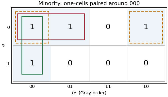
Three essential pairs in the three-input minority Karnaugh map
. Details. The pairs giveGenerate with three NOT gates. Then useDe Morgan laws show that the final NAND gate computes the required disjunction of the three products. This uses three two-input NAND gates and one three-input NAND gate, besides the input inverters. If only two-input NAND gates are available, replace the final three-input gate by , , .
The three pairs are essential: the one-input assignments each have only as an adjacent one-cell, so no pair can be omitted from this disjunctive normal form.
Write the inputs as and . Each row compares the represented value of with all four values of . In Gray code order along both axes, the Karnaugh map isThe equality cases lie on the diagonal and are all one. A complete row of ones at and a complete column at provide useful checks. The outlined groups are used in the next part.
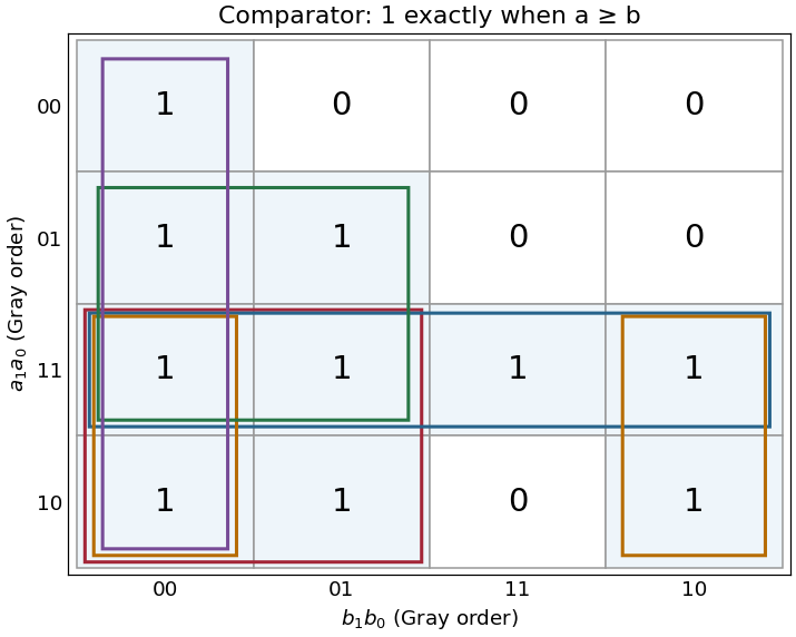


The five maximal four-cell groups give the disjunctive normal formFor example, the group wraps between columns and in the bottom two rows. No group of eight cells is entirely one. The five terms are precisely the prime implicants, and each is essential: respectively, the cells are covered by no other prime implicant. Any disjunctive normal form can have its terms enlarged to prime implicants without increasing its size. Therefore all five displayed terms are necessary, proving minimality in number of products; each needs two literals, also giving ten literals in a minimal cover.
For an implementation with AND gates and NOT gates, call these five products . Form the shared complements , calculate each with an AND gate, invert every , and useA five-input conjunction can be replaced by four two-input AND gates. This direct implementation uses nine two-input AND gates and eight NOT gates. That is a valid realization of the minimal disjunctive normal form, rather than a claim that this particular gate count is globally optimal among all factored circuits.
By matrix multiplication, . A potentially nonzero term requires because is a diagonal matrix, and because is a diagonal matrix. For these requirements cannot both hold. Thus every summand is zero and whenever .
The diagonal matrix entry is . Only can contribute, so . This also shows that the product is a diagonal matrix, with its diagonal obtained by entrywise multiplication of the two diagonals.
Repeatedly applying the previous product rule givesFormally, the result holds for ; multiplication by preserves the zero off-diagonal matrix entries and multiplies each diagonal matrix entry by , proving the induction step.
The characteristic polynomial is . Its distinct eigenvalues are and . For either eigenvalue , the vector is an eigenvector, since .
ChooseThe determinant of is , soIts columns being eigenvectors gives , and left multiplication by proves .
The initial vector records both initial Fibonacci numbers: . For ,Conversely this vector recurrence forces the second component to be the preceding first component and forces their sum to be the next first component, recovering the scalar recurrence and its initial conditions. Iterating, or using mathematical induction, yields for every .
The diagonalization gives and hence : the intervening factors cancel. The diagonal matrix power has entries . Since and ,Reading the second component gives the Binet formulaThe derivation includes , and the expression gives , consistent with the specified indexing.
Left multiplication by an elementary matrix adds a multiple of row one to its designated target row. The first-column entries below the pivot are , so , , . The corresponding row operations are , , and . Since none changes row one, their sequential application gives the required three eliminated first-column entries and the displayed remaining entries.
The second pivot is two. Row three has second entry two, so subtract row two; row four has second entry minus two, so add row two. Therefore , . Their trailing row pairs become and , respectively; the zero in the third pivot position is why a later row interchange is needed.
Let denote the matrix unit with one at position and zero elsewhere. The five inverses areThus each is the identity matrix with only the indicated off-diagonal matrix entry altered. These inverses reverse the corresponding row additions; no row scaling or permutation is involved.
The permutation matrix isRows three and four of the identity matrix have been interchanged, so left multiplication interchanges those rows of any matrix.
Left multiplication by interchanges rows three and four; applying it twice restores every row. Equivalently, it sends the standard basis vectors to each other and fixes , so its square fixes a basis. .
The th column of is . The permutation matrix fixes and interchanges , so these columns are . They are exactly the first, second, fourth and third columns of . Thus right multiplication by interchanges columns three and four, leaving the others unchanged.
The first left multiplication swaps rows three and four. The final right multiplication swaps columns three and four, restoring the two diagonal ones to their diagonal positions while exchanging the earlier entries of the two rows. ThereforeThe two specified zeros at positions and are important. Conjugation by this permutation matrix preserves this restricted lower triangular pattern; it would not preserve lower triangularity for an arbitrary matrix with a nonzero entry.
Write and put . Inserting between adjacent elimination matrices givesEach has the restricted lower triangular pattern in part (b)(v). Also , as direct multiplication verifies. Hence every is lower triangular. Their product is lower triangular by the allowed closure property, proving the required Pivoted LU decomposition with .
Explicitly,The multipliers in rows three and four of are permuted along with the rows of ; simply keeping the unpermuted elimination multipliers would give the wrong product. This is the mechanism in conjugating elimination matrices across a row permutation.
Replacing row one by does not change the determinant: adding a multiple of another row preserves a determinant. It produces first row , whose cofactor minor is the three-dimensional identity matrix. Thus the determinant is .
The columns are homogeneous coordinate vectors of the four vertices. Subtracting the first column from each other column preserves the determinant and reduces its magnitude to the absolute determinant of the three edge vectors based at . That absolute determinant is the parallelepiped volume. A tetrahedron occupies one sixth of that parallelepiped, so in cubic coordinate units.
A unit vector along the line is . Reflection preserves the orthogonal projection onto that line and negates its perpendicular component. Therefore andAs checks, , , and . Its determinant is minus one, as expected for a planar reflection matrix.
Gaussian elimination gives the row operations , , , producing the lower three rows , , . Subtract the new row two from row three and add three times row two to row four; the remaining nonzero row is . Move it above the zero row and finish elimination to obtainThe pivot columns are one, two and three. Row operations preserve the linear dependence relations among columns, so the corresponding columns of the original matrix form a basis for the column space, which is the image of the linear map:In particular, the matrix rank is three. Columns of the reduced matrix itself would generally give a different subspace, so the original columns must be used.
The reduced row echelon form gives , , and . Taking gives every vector in the null space as . Thus a basis for the kernel of the linear map isDirect multiplication gives . The rank-nullity theorem also checks the count: matrix rank three plus nullity one equals the domain dimension four.
No. The nonzero vector is in the kernel of the linear map, so although . A linear map is injective exactly when its kernel consists only of zero.
Use natural deduction with labelled temporary assumptions. Assume under label , then under label , then under label . Two applications of the modus ponens rule give and . The negation elimination rule gives , and the supplied reductio ad absurdum rule discharges to conclude .
Discharge using the implication introduction rule, obtaining under . Discharge with the implication introduction rule, obtainingAll three temporary assumptions have now been discharged; no premise remains.
Keep the four given premises in context and assume under label . The modus ponens rule applied to the first two premises gives and . Apply the disjunction elimination rule to as follows.
Under a case assumption , the premise gives by the modus ponens rule. Together with , the negation elimination rule gives , and the supplied logical falsity elimination rule gives . Under the other case assumption , the required conclusion is already available. Discharge both case assumptions with the disjunction elimination rule to conclude .
Finally discharge with the implication introduction rule, giving . The premise is not needed: a derivation is permitted to leave a premise unused.
Use the disjunction elimination rule on the outer disjunction. In its left branch, assume and apply the disjunction elimination rule again: from a case assumption , the disjunction introduction rule gives ; from a case assumption , the premise and the modus ponens rule give , then the disjunction introduction rule gives . Discharging those two inner case assumptions yields under the left outer branch.
In the right outer branch, assume . A case assumption gives by the disjunction introduction rule. A case assumption , together with the premise , gives by the negation elimination rule, and then by logical falsity elimination rule. Discharge these inner case assumptions with the disjunction elimination rule.
Both outer branches now have the same conclusion. Discharge the two outer case assumptions with the disjunction elimination rule to obtain under exactly the stated premises.
Assume under label , under label , and under label . A temporary case assumption gives by the modus ponens rule using . A temporary case assumption gives by the modus ponens rule using . The disjunction elimination rule discharges these case assumptions and concludes under .
Apply the implication introduction rule three times, discharging , then , then . The resulting theorem isThe displayed parentheses make explicit the right association of the source formula.
Let abbreviate . Suitable rules areTheir derivations require no new axiom. For introduction, apply the conjunction introduction rule to the two premises, obtaining , which is exactly the abbreviation. For left and right elimination, unfold the abbreviation and apply the corresponding conjunction elimination rule. These are therefore derived rules for the NOR connective.
An equivalent subproof presentation of introduction permits one subproof from assumption to and another from assumption to : use the negation introduction rule to discharge each assumption, then apply the conjunction introduction rule. If elimination is desired in contradiction form, combine the left projection with , or the right projection with , using the negation elimination rule. All these presentations reduce directly to the permitted rules.
Write . We derive the two disjunction introduction rules and the disjunction elimination rule without using any disjunction rule inside the derivations.
For left introduction, start with and temporarily assume . The conjunction elimination rule gives , and the negation elimination rule gives . Discharge the temporary conjunction by the negation introduction rule, concluding . For right introduction, start with and use the right conjunction elimination rule to obtain instead. Thus either input derives the required encoded disjunction.
For elimination, suppose is available, together with a derivation of from an additional assumption and a derivation of from an additional assumption . Keep their common external context fixed. Temporarily assume under label . Temporarily assume under label and insert the supplied first branch derivation to obtain . Negation elimination rule gives , so negation introduction rule discharges and gives . Repeat with a temporary assumption under label and the supplied second branch derivation, discharging to obtain .
Conjunction introduction rule now gives . Its negation gives by negation elimination rule. The supplied reductio ad absurdum rule discharges and yields . This discharges the two branch assumptions as required and proves the encoded elimination rule. Its last step uses classical propositional logic; the same encoded elimination principle is not generally available in Intuitionistic propositional logic.
Articles were limited to the first 100 out of 508 total.
Articles by others on the same topic
There are currently no matching articles.