An ultramicrotome is a precision cutting instrument for producing very thin sections or successively exposing new specimen faces for electron microscopy. Ultramicrotomy combines a controlled specimen feed with a cutting stroke across a sharp diamond knife or suitable glass knife. A polymer block is one example of a specimen for materials work. JEOL describes preset feeds of tens of nanometres and notes that actual section thickness can differ from the setting.[ref]
Ultramicrotomy by JEOL. Definition, specimen advance and diamond-knife cutting description; thickness dependence on material and temperature
The mechanism must distinguish the feed direction, which sets the intended removed thickness, from the much longer cutting stroke across the block. Section collection supports transmission electron microscopy; an in-chamber version supports serial block-face scanning electron microscopy by imaging the remaining surface.
For an original cutting-budget example, suppose a polymer block is advanced by per cut. After 250 uniform cuts the nominal removed thickness isIf one entire section is lost during collection, its neighbors' centers are apart rather than , assuming all feeds were correct. The total removed thickness remains ; the lost section leaves an observation gap. Recording only the number of surviving images would conceal that gap.
A physical check compares the intended feed with an independent thickness or accumulated-depth measurement, while recording specimen and knife conditions. A fine actuator increment alone does not establish the actual section thickness. Compression, uneven cutting and missing sections affect the geometry subsequently assigned to an image stack.
Ultramicrotomy prepares extremely thin physical sections by advancing a specimen block through a controlled increment and cutting across it with an ultramicrotome. A diamond knife or suitable glass knife removes the section; collected sections can then be examined by transmission electron microscopy. The instrument's feed setting and the geometry of the recovered section are related quantities, but they need not be equal. JEOL explicitly notes dependence on specimen material and temperature.[ref]
Ultramicrotomy by JEOL. Definition and specimen-feed description; actual-thickness dependence on resin and environmental temperature
For a materials example, consider a polymer block containing an initially -long marked interval parallel to the cutting direction. Suppose the recovered section measures along that interval, with unchanged transverse width. Its section compression is . Under an explicitly ideal volume-conserving model, a nominal layer would then have recovered thicknessThe altered area and thickness give the same model volume: . This is an original diagnostic calculation, not a universal correction rule. Material loss, transverse strain or nonuniform deformation would invalidate the model.
A motivating preparation check therefore compares dimensions of recognizable material features before cutting and in the recovered section, while recording cutting direction and specimen conditions. An independent thickness measurement tests whether the feed is a good depth calibration. Image registration can align section images but cannot generally reverse unknown physical deformation. For serial-section electron microscopy, preserve section order and gaps in the image stack as well as the chosen image stack axis calibration.
Section compression is shortening of a cut section relative to the corresponding specimen-block dimension, usually measured parallel to the cutting direction in ultramicrotomy. It is a physical deformation introduced during preparation, so an accurately calibrated microscope can still measure a distorted specimen. Manufacturer guidance for polymer sectioning connects reduced compression with smaller knife wedge angles, while noting the resulting greater sensitivity of the cutting edge.[ref]
Ultramicrotomy Techniques for Materials Sectioning by Leica Microsystems. How to prepare high-quality sections of polymers: wedge-angle tradeoff
Let be a reference length in the block and its recovered section length along the same direction. Define a positive compression fractionThe corresponding engineering strain is . State this sign convention: a reported positive percentage compression and a negative longitudinal strain can describe the same shortening.
For an original geometrical model, a feature recovered as has . If transverse dimensions are unchanged and the shortening is uniform, an originally circular feature becomes an ellipse with axis ratio . Its area becomes of the original, not : only one direction was shortened. Under the additional assumption of volume conservation, a nominal layer would have thicknessNeither transverse constancy nor volume conservation is automatic. Material loss, cracking, relaxation and nonuniform deformation can invalidate the model; section length alone cannot establish recovered thickness.
A useful materials check compares recognizable features in the block face and collected section, recording cutting direction, knife wedge angle, knife clearance angle and specimen conditions. Repeating the comparison at several positions tests whether one compression fraction is adequate. Under the simple model above, expanding the shortened coordinate by would reverse the geometrical shortening, but this is a model-based correction rather than an extra observation. Image registration can align features without proving that it has recovered their original shapes.
A diamond knife uses a sharpened diamond edge to cut ultrathin sections in ultramicrotomy. The edge's geometry and condition affect the force applied to the specimen and the resulting section. JEOL describes its use for hard inorganic materials and for obtaining uniform sections from resin specimens.[ref]
The knife wedge angle is the angle between the blade faces. It differs from the knife clearance angle, which concerns how the blade is oriented relative to the freshly cut surface. Manufacturer descriptions include and knife families, with the lower-angle design promoted for reduced section compression and a higher-angle design discussed for hard materials.[ref]
Ultra diamond knives by DiATOME. ultra35° and ultra45° manufacturer descriptions; materials applications
For an original ideal symmetric wedge of included angle , the blade width a distance behind the apex isAt , this gives for and for . The wider ideal wedge has about 31% more material behind the edge at that distance. This illustrates a geometry tradeoff; it does not predict a 31% difference in cutting force or assert the exact profile of a commercial knife.
A useful materials experiment compares otherwise matched cuts while recording knife orientation, feed and specimen condition, then measures section dimensions and surface defects. A cut stripe that repeats at the same lateral position suggests an edge-related artifact worth checking. Diamond hardness alone does not guarantee an undamaged edge or an undistorted section.
The knife clearance angle is the angle between the blade face facing the newly cut specimen surface and that surface, measured in the cutting cross-section. It describes how the knife is oriented. The knife wedge angle instead describes the angle between the two blade faces at the edge. Tilting the holder changes clearance without changing the blade's intrinsic wedge geometry.[ref]
Knife Angle in Microtomy by Charles W. Scouten. Ideal versus compromise; Figure 1 and discussion of the specimen-side bevel
Positive clearance lets the trailing blade face move clear of the cut surface. With insufficient clearance, that face can press or rub against the specimen instead of clearing it. Excessive tilt changes the cutting geometry too; simply maximizing clearance is not a general route to an undistorted section.[ref]
Knife Angle in Microtomy by Charles W. Scouten. Consequences of too shallow an angle and Consequences of too steep an angle
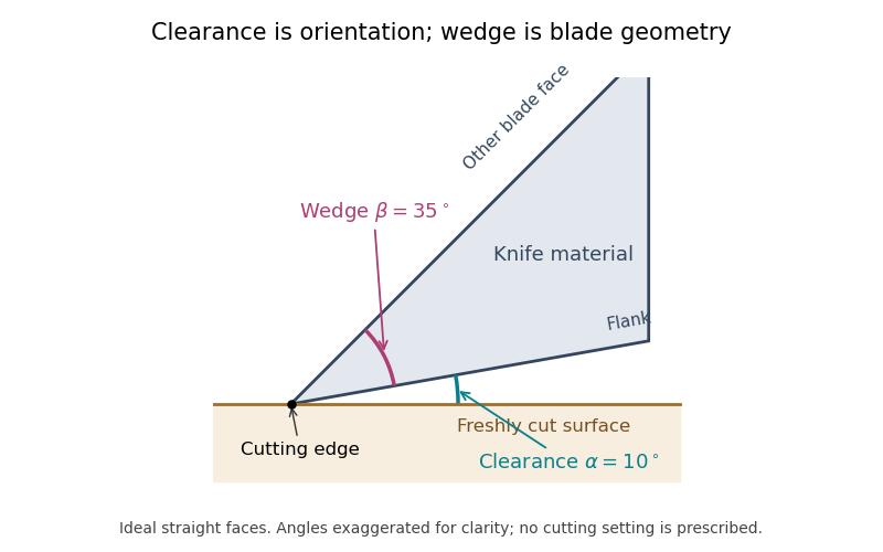

For the ideal straight faces in the diagram, let be clearance and the wedge angle. Their upper-face orientation relative to the cut surface is . With the chosen and , it is . Tilting the whole blade by gives clearance and upper-face orientation , while stays .
There is also a simple gap calculation. A point a projected distance behind the cutting edge lies above the ideal cut plane. At and , . Real bevels and specimen deflection complicate this geometry, and the holder's indicated angle must be interpreted using its manufacturer's convention. Comparing section compression and surface defects at otherwise matched conditions can test the consequences of an angle change; the angle scale alone is not a measurement of section quality.
The knife wedge angle is the included angle between the blade faces meeting at a cutting edge. It is a property of the edge geometry, distinct from the knife clearance angle produced by orienting the knife relative to the specimen. A final bevel can have a different angle from the broader blade body, so identify which faces define a quoted angle.[ref]
Knife Angle in Microtomy by Charles W. Scouten. Ideal versus compromise: final bevel and cross-sectional wedge
In ultramicrotomy, the wedge angle affects the tradeoff between reducing section compression and supporting a durable edge. Manufacturer descriptions distinguish and diamond knives; the lower-angle family is described as reducing compression. Guidance for polymer and brittle-material sectioning also emphasizes that lower angles leave a more sensitive edge and that some hard materials favor a larger angle.[ref]
Ultra diamond knives by DiATOME. ultra35° and ultra45° descriptions
[ref]Ultramicrotomy Techniques for Materials Sectioning by Leica Microsystems. How to prepare high-quality sections of polymers; brittle-material discussion
An original geometric comparison makes the difference concrete without pretending to predict cutting forces. On each face of an ideal wedge, mark a point a distance from the apex. The distance between those points is the base of an isosceles triangle:For , this gives at and at . The larger angle puts more material between the faces at that distance from the apex. This geometry is not an empirical law relating wedge angle to force, friction or a particular compression percentage.
Changing knife clearance angle rotates both blade faces together and leaves their included angle unchanged. Conversely, selecting a different wedge geometry need not mean that the same holder setting gives the same cutting conditions. A meaningful comparison records both angles, specimen material, feed and observed section compression. The two angle names should therefore remain separate even when an instrument discussion informally calls either one the knife angle.
Articles by others on the same topic
There are currently no matching articles.