X-ray crystallographic structure inference is an inverse problem: infer a crystal structure from measured X-ray diffraction. A proposed unit cell and atomic basis of a crystal predict a pattern; structure determination asks which proposals survive comparison with that pattern. The useful separation is between directions and strengths. Peak positions constrain the reciprocal lattice and hence interplanar spacings; relative wave intensities constrain the motif through the crystal basis structure factor. Knowing a repeat distance does not locate all the chemical atoms within that repeat.
The lattice constant from two indexed reflections example isolates the geometric inference. Basis intensities and phase ambiguity then holds the translations fixed while changing the motif. Even complete, noiseless wave intensity data need not determine all wave phases: this is the phase problem. Chemical composition, symmetry, and additional measurements can supply constraints beyond the original pattern.[ref]
Phase problem. Online Dictionary of Crystallography by International Union of Crystallography; Definition and Methods of solution: intensities determine structure-factor magnitudes but not phases; additional structural information enters phase estimation
Choose an original simulated model: a primitive cubic lattice with one identical point scatterer per primitive unit cell, edge , and incident X-ray wavelength . These are stipulated lengths, not measurements of sodium chloride. Suppose orientation information has already assigned the two observed reflections the Miller indices and . The detector deflection is , where is the Bragg angle.
Use the existing interplanar spacing formula and Bragg's law, with higher diffraction orders absorbed into the reflection indices:The simulated reflection has , hence . The reflection has , hence . Their squared sines are and , in ratio . Substituting the unrounded angles independently givesAgreement tests a proposed indexing and scale together; disagreement would prompt checks of the indexing, wavelength, angular zero, or the assumed unit cell geometry.
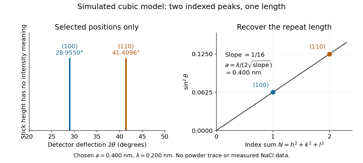
Two indexed reflections recover the same cubic repeat length
. Original simulation with and . Left: selected and positions on a detector-deflection axis; equal stick heights are only markers. Right: their squared sines lie on the line of slope . These are selected reflections, not a complete scan, a powder trace, or measured sodium chloride data. Details.
Two peak positions alone do not establish the indexing. Assigning the same two angles to and would give and instead. More reflections, orientation information and systematic absences help discriminate such assignments. An unobserved reflection can be inaccessible, weak or extinguished by the atomic basis; absence is not automatically evidence for a larger interplanar spacing.
Absolute scale also requires measurement calibration of the wavelength. To first order, differentiation of the inferred length giveswith angular changes in radians. A stipulated detector-zero error , with correct wavelength, biases the first inferred edge downward by approximately and the second by . A common angular offset therefore need not cancel when two inferred lengths are compared. These are model sensitivity estimates, not historical instrument uncertainties.
Keep the cubic translations above, but attach an atomic basis with A at fractional crystal coordinates and B at . Stipulate real, angle-independent relative scattering amplitudes and . Neglect wave absorption, repeated crystal scattering and thermal motion. This is a point-scatterer model under the Born approximation, not a claim about the scattering strengths of named elements. Its crystal basis structure factor isHere is a dimensionless squared motif amplitude. Comparing it with measured integrated wave intensities requires the experimental geometry and detector response as well. The algebra follows directly by multiplying by its complex conjugate; the cross term records wave interference between the two sites.
With , reflections with even have , whereas odd gives , a ratio of . With , the first four values instead are . Their geometrically possible positions are unchanged, although their strengths change. For equal stipulated amplitudes and , the odd- amplitude vanishes exactly: an example of a systematic absence. Different motif weights can thus expose a repeat that equal weights conceal.
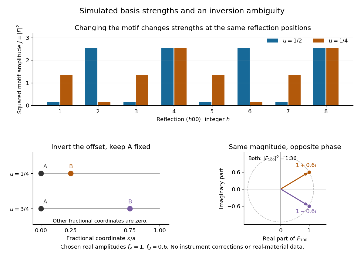
The motif changes intensities, while inversion can preserve them
. Original point-scatterer simulations with and . Top: the same reflection labels have different squared motif amplitudes for and . Bottom left: moving B from to inverts its offset modulo a translation. Bottom right: the two crystal basis structure factors are complex conjugates, , with the same squared modulus . No detector profiles or real-material measurements are plotted. Details.
The same formula also proves an ambiguity: and give identical for every integer , because . Yet changes from to , reversing its wave phase. This particular ambiguity is inversion of the motif; it does not prove that these two simple motifs are distinct chemical substances. The conclusion is conditional on the stipulated real scattering amplitudes.
The phase problem is the loss of the wave phases of the crystal basis structure factors when an experiment records their squared magnitudes. Write . A Fourier series reconstruction of a periodic electron density uses both and , whereas an ordinary wave intensity measurement supplies only . Estimating the missing phases therefore needs additional constraints or measurements.[ref]
Phase problem. Online Dictionary of Crystallography by International Union of Crystallography; Definition: missing structure-factor phases prevent reconstruction of atomic positions; Methods of solution: estimates are tested against observations
There is also an unavoidable choice of origin. Translating all motif positions by the same fractional crystal coordinate vector multiplies by without changing . The physical arrangement is unchanged. A reconstructed coordinate list must therefore distinguish a coordinate convention from information actually recovered from the measurements.
William Lawrence Bragg's 1913 structure paper connects a slit-selected beam, an oriented crystal and an ionization chamber to strength-versus-angle curves. Repeated sine ratios and matching absorption coefficients identify common radiation. Narrower slits resolve blended lines. Absolute wavelengths remain undetermined there; intercrystal comparisons first give relative scales. The Bragg crystal reflection experiment of 1913 covers the alignment controls.[ref]
The Structure of Some Crystals as Indicated by their Diffraction of X-rays by William Lawrence Bragg. pp. 268–272, especially Fig. 16: angular ionization scans, order/absorption comparison, slit resolution and wavelength-scale limitation
William Henry Bragg's 1915 Bakerian lecture, X-rays and Crystal Structure, separates the geometric and intensity arguments. Its Figure 9 compares reflection positions and strengths from three sodium chloride orientations; odd and even diffraction orders differ in strength along one orientation. The interpretation uses alternating scattering layers. Later, the calcite example identifies an internal oxygen coordinate that symmetry alone cannot fix. Improved wave intensity measurements revise a previously rough estimate. Thus a lattice assignment can precede determination of positions inside the unit cell; intensity interpretation also has experimental and theoretical limits. This is the father's 1915 lecture, distinct from the joint 1913 reflection paper.[ref]
Articles by others on the same topic
There are currently no matching articles.