Concentration inequalities are mathematical inequalities that provide bounds on how a random variable deviates from a certain value (typically its mean). These inequalities are essential in probability theory and statistics, particularly in the fields of machine learning, information theory, and statistical learning, because they help analyze the behavior of sums of random variables, as well as the performance of estimators and algorithms. There are several well-known concentration inequalities, each suitable for different types of random variables and different settings.
Ross's conjecture is a hypothesis in the field of mathematics, specifically in number theory and combinatorics. It pertains to the behavior of certain sequences and their asymptotic properties. The conjecture was introduced by the mathematician John Ross in the early 2000s and explores the relationships between additive and multiplicative number theory. The specifics of the conjecture can vary based on its context, but it generally deals with conjectures regarding sums and products of integers or sequences.
The Binomial sum variance inequality is a result in probability theory that deals with the variance of the sum of independent random variables. While there are various forms of inequalities related to sums of random variables, one common form associated with the binomial distribution is the variance of a binomially distributed random variable. For a random variable \(X\) that is binomially distributed, i.e.
Popoviciu's inequality is a result in statistics concerning the variances of random variables. Specifically, it provides a bound on the variance of a random variable in relation to its range.
The term "Historie" can refer to different contexts depending on the subject matter. Here are a few interpretations: 1. **General Meaning**: In many languages, such as German and French, "Historie" simply means "history." It encompasses the study of past events, particularly in human affairs. 2. **Specific Works**: "Historie" may also refer to specific historical texts or literary works.
"Starry Messenger" is a picture book by the renowned author and illustrator Matthew Winner. It is a beautifully illustrated work that introduces young readers to the life and ideas of the famous astronomer and physicist Galileo Galilei. The book focuses on Galileo's curiosity about the universe, his observations of the stars and planets, and how his discoveries paved the way for modern astronomy. The story emphasizes themes of exploration, inquiry, and the importance of questioning the world around us.
"Death Wish" is the 18th episode of the second season of **Star Trek: Voyager**, which originally aired on February 3, 1996. This episode is notable for its exploration of themes such as free will, the value of life, and the ethics surrounding assisted suicide. In "Death Wish," the Voyager crew encounters a mysterious being known as Q, portrayed by John de Lancie, who is part of the Q Continuum.
The Nicolaus Copernicus Monument in Montreal is a commemorative statue dedicated to the famous Renaissance astronomer Nicolaus Copernicus, known for his heliocentric model of the universe, which posited that the Earth and other planets orbit the Sun. The monument is located in the neighborhood of Little Italy, near the Church of the Madonna della Difesa.
"Don't Fear the Roofer" is a phrase that can refer to various contexts, but it is most notably associated with the television show "The Office." In the show's third season, there is an episode titled "Don't Fear the Roofer," where the character Michael Scott, played by Steve Carell, searches for a roofer to help him out after a roofing problem arises at the office.
"Stephen Hawking's Favorite Places" is a documentary series featuring renowned physicist Stephen Hawking as he explores various topics related to science and the universe. The series is presented as a virtual journey where Hawking uses a combination of animation and stunning visuals to explain his favorite cosmic locations and concepts. The show combines Hawking's scientific insights with imaginative visualizations to make complex ideas more accessible to a general audience.
"Superhero Movie" is a 2008 comedy film directed by Craig Mazin. It is a parody of the superhero genre, particularly focusing on the successes of movies like "Spider-Man" and "X-Men." The film follows a character named Rick Riker, who gains superpowers after being bitten by a genetically altered dragonfly and then becomes the superhero "The Dragonfly." The movie employs a satirical approach, using humor to mock various tropes and clichés found in superhero films.
"Numbers" (often stylized as "Numb3rs") is a television series that aired from 2005 to 2010. The show combines crime drama with mathematics, as it follows FBI agent Don Eppes and his brother Charlie Eppes, a mathematics prodigy, who uses his mathematical skills to help solve crimes. Here are the main characters: 1. **Don Eppes (played by Rob Morrow)** - An FBI agent and the older brother of Charlie.
"Supergiant" can refer to a couple of different concepts, primarily in the contexts of astrophysics and gaming: 1. **Astrophysics**: In astronomy, a supergiant is a very large and luminous star that is much brighter and more massive than the Sun. Supergiants are typically classified as spectral types O, B, A, or F and can have diameters up to 1,000 times that of the Sun.
Paul Guldin (also known as Paul Guldin or Paul Guldin the Elder) was a notable figure in the field of mathematics during the 16th and 17th centuries. He is best known for his work related to geometric concepts, particularly in relation to volumes of solids of revolution. Guldin's work laid the groundwork for further developments in calculus and mathematical analysis.
Robert Russell was an Irish mathematician known for his contributions to the field of mathematics during the 19th century. He is often associated with developments in mathematical analysis and geometry. While specific details about his life may not be widely documented, his work, along with that of his contemporaries, contributed to the advancement of mathematical thought during that period.
Tom H. Koornwinder is a prominent Dutch mathematician known for his contributions to various areas of mathematics, particularly in special functions, mathematical analysis, and orthogonal polynomials. He has been involved in research that explores connections between mathematics and theoretical physics, and he has published numerous papers and articles on these topics.
Allan Hill can refer to multiple things depending on the context, but it is commonly associated with: 1. **Geographical Feature**: Allan Hill may refer to a specific hill or geographical location in a certain region. Many places have similar names, so context is important. 2. **Personal Name**: Allan Hill could also refer to individuals with that name. For example, there might be notable people in various fields such as sports, academia, or business.
Pinned article: Introduction to the OurBigBook Project
Welcome to the OurBigBook Project! Our goal is to create the perfect publishing platform for STEM subjects, and get university-level students to write the best free STEM tutorials ever.
Everyone is welcome to create an account and play with the site: ourbigbook.com/go/register. We belive that students themselves can write amazing tutorials, but teachers are welcome too. You can write about anything you want, it doesn't have to be STEM or even educational. Silly test content is very welcome and you won't be penalized in any way. Just keep it legal!
Intro to OurBigBook
. Source. We have two killer features:
- topics: topics group articles by different users with the same title, e.g. here is the topic for the "Fundamental Theorem of Calculus" ourbigbook.com/go/topic/fundamental-theorem-of-calculusArticles of different users are sorted by upvote within each article page. This feature is a bit like:
- a Wikipedia where each user can have their own version of each article
- a Q&A website like Stack Overflow, where multiple people can give their views on a given topic, and the best ones are sorted by upvote. Except you don't need to wait for someone to ask first, and any topic goes, no matter how narrow or broad
This feature makes it possible for readers to find better explanations of any topic created by other writers. And it allows writers to create an explanation in a place that readers might actually find it.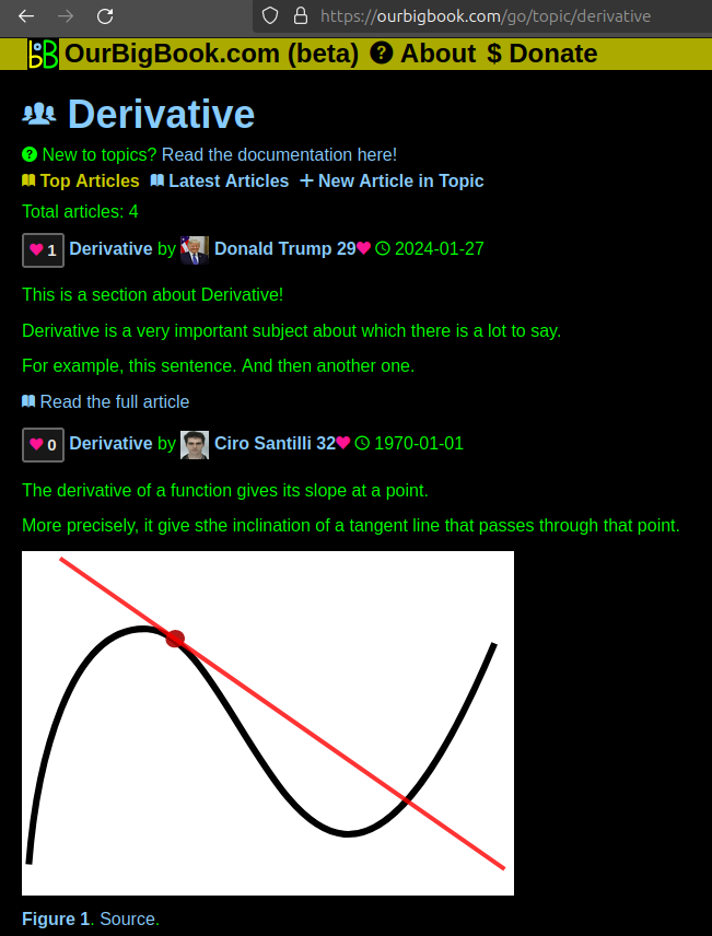
Figure 1. Screenshot of the "Derivative" topic page. View it live at: ourbigbook.com/go/topic/derivativeVideo 2. OurBigBook Web topics demo. Source. - local editing: you can store all your personal knowledge base content locally in a plaintext markup format that can be edited locally and published either:This way you can be sure that even if OurBigBook.com were to go down one day (which we have no plans to do as it is quite cheap to host!), your content will still be perfectly readable as a static site.
- to OurBigBook.com to get awesome multi-user features like topics and likes
- as HTML files to a static website, which you can host yourself for free on many external providers like GitHub Pages, and remain in full control

Figure 3. Visual Studio Code extension installation.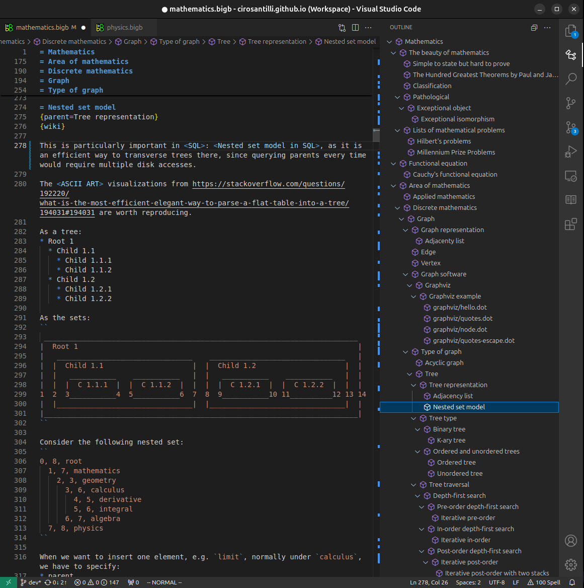
Figure 4. Visual Studio Code extension tree navigation.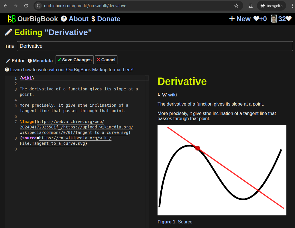
Figure 5. Web editor. You can also edit articles on the Web editor without installing anything locally.Video 3. Edit locally and publish demo. Source. This shows editing OurBigBook Markup and publishing it using the Visual Studio Code extension.Video 4. OurBigBook Visual Studio Code extension editing and navigation demo. Source. 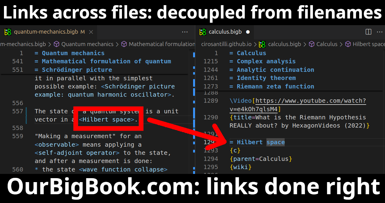
- Infinitely deep tables of contents:

All our software is open source and hosted at: github.com/ourbigbook/ourbigbook
Further documentation can be found at: docs.ourbigbook.com
Feel free to reach our to us for any help or suggestions: docs.ourbigbook.com/#contact