Gaussian pulse time-gate energy fraction
ID: gaussian-pulse-time-gate-energy-fraction

The Gaussian pulse time-gate energy fraction is the share of an isolated pulse's laser pulse energy admitted by a finite time window. The result below acts on incident optical radiant power. Let be the power full width at half maximum, and first place the pulse centre and the detection time gate centre at zero.
A detection time gate need not collect the whole pulse. Integrating the same profile only over gives the Gaussian pulse time-gate energy fractionwhere is the error function. A gate as wide as the power full width at half maximum collects only , or 76.10% of the pulse energy. The pulse has nonzero Gaussian tails outside that interval. A real readout's impulse response can extend the required integration window further.
Alignment adds a parameter. Let the pulse centre be , the gate centre be , and write the Gaussian gate centring error as . Put . Integrating the normalized Gaussian pulse profile over the gate givesAt the two error function terms reduce to the centred formula above. With and , the captured fraction drops to . The pulse centre then lies on a gate edge. Merely keeping the gate width fixed does not keep its collected energy fixed.
The gate works best when centred. With the centred energy-normalized pulse profile and , differentiation of givesA Gaussian function is an even function about its centre and decreases with distance from that centre. Thus for , and symmetry gives the opposite sign for . The same argument proves that a centred interval maximizes mass for an even unimodal density; unimodality supplies the required monotonicity.
A centred gate of width captures of the energy. Solving gives for 99% capture in this ideal model. The requirement changes if the centring error is nonzero.
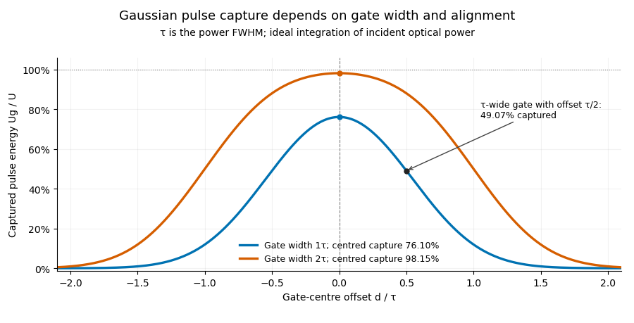

Pulse timing jitter can therefore create variation in gated energy even when every full pulse has the same . A wider gate reduces this loss but also changes admitted background and the chance of including neighbouring pulses. Measure the timing and detector response associated with the chosen gate.
For a detector modeled as a linear time-invariant system, its recorded waveform is a convolution of the optical input with its impulse response. NIST tested avalanche photodiode radiometers with roughly optical pulses, recorded their responses with an oscilloscope, and convolved measured responses with longer Gaussian inputs to estimate corrections. The detector and amplifier were characterized together.[ref]
Calibration Service for Low-level Pulsed-Laser Radiometers at 1.06 µm: Pulse Energy and Peak Power by Rodney W. Leonhardt. §§6.1–6.2, printed pp. 13–15: short-pulse excitation, sampling readout and numerical convolution
A gate applied to that electrical waveform must use the readout model rather than assuming the optical fraction is unchanged. New to topics? Read the docs here!