For elastic scattering with and ,The smallest nonzero diffraction angle is determined by the shortest reciprocal-lattice vector.
This reciprocal-lattice condition is equivalent to Bragg's law, expressed in terms of the lattice-plane spacing and the wavelength.
Bragg's law selects directions of constructive interference in coherent elastic scattering from equally spaced lattice planes:Here is the perpendicular interplanar spacing, the incident wavelength, the positive integer diffraction order, and the Bragg angle, measured between the incoming beam and the lattice planes. The scattering deflection, between incoming and outgoing propagation directions, is . Thus a plotted detector angle must be halved before insertion into Bragg's law. The in the parent elastic Bragg scattering condition denotes the full deflection; the present denotes half of it. [ref]
Bragg's law. Online Dictionary of Crystallography, Bragg's law, Definition: spacing, wavelength, glancing angle and reflection order
The lattice planes organize wave interference throughout a crystal structure; they are not literal metal mirrors or separate reflecting surfaces. The picture assumes elastic scattering, hence an unchanged wavelength, and sufficiently stable relative wave phases across the contributing lattice planes. X-ray wavelengths comparable with atomic interplanar spacings make these directions experimentally accessible. The sine cannot exceed one: an order exists geometrically only if . For , even the first diffraction order is inaccessible. A geometrically possible direction need not have nonzero wave intensity; the crystal lattice structure factor and crystal basis structure factor also matter. [ref]
Structure factor. Online Dictionary of Crystallography by International Union of Crystallography; Definition and Derivation: coherent addition of the atoms within the unit cell
The Bragg angle is the glancing angle from the incident beam to the selected lattice planes, with . If is instead the angle from the beam to the plane normal, and Bragg's law becomes . Defining the angle explicitly prevents a sine-versus-cosine error as well as a factor-of-two error in the detector deflection.
Choose and as an illustrative model, not historical measurements. For the first diffraction order,The second diffraction order has and ; the third would require and is impossible. These are different diffraction orders of the same interplanar spacing at the same wavelength.
Conversely, a first-order reflection at a measured deflection gives the interplanar spacingUsing recovers . This is the useful reversal: a known wavelength turns an angular measurement into an atomic length. An unassigned diffraction order or an unknown wavelength prevents that single measurement from determining uniquely.
For an isotropically compressed cubic crystal, . Differentiating Bragg's law at fixed wavelength gives the displayed derivative. Constant isothermal compressibility gives , not an exactly linear lattice parameter. The integrated prediction presumes no intervening structural phase change.
Compare two rays scattered into parallel outgoing directions from neighboring lattice planes. In the diagram, lies on the upper plane and on the lower plane, directly beneath with . Draw through the incoming and outgoing equal-wave phase fronts, perpendicular to their respective rays. They meet the lower ray at and . Each right triangle gives , so the lower ray travels the extra distanceThe resulting phase difference is . Constructive interference requires , which proves Bragg's law in this ray construction. Comparing equal-wave phase fronts, rather than arbitrary ray endpoints, is what makes the distance comparison meaningful.
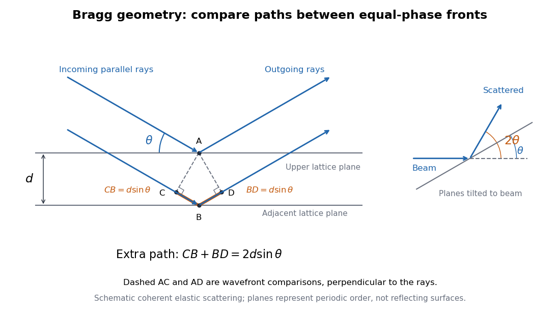
Bragg rays, extra path, and the distinction between the glancing angle and scattering deflection
. Original schematic of coherent elastic scattering. The orange segments give the extra path ; dashed segments compare equal-wave phase fronts. The separate angle sketch shows why the outgoing beam is deflected by when the Bragg angle is . The illustrated angle is schematic. Details.
The same geometry connects to the reciprocal lattice. With wavenumber , the elastic Bragg scattering condition gives a transfer magnitude . A reciprocal vector normal to these lattice planes has . Equating them again yields Bragg's law. The ray and reciprocal lattice descriptions therefore express the same wave phase matching.
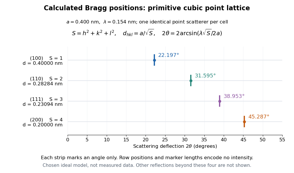
Consider a chosen primitive cubic lattice with and one identical point scatterer per primitive unit cell. Retain the incident wavelength . This is an ideal point model. Its reciprocal lattice vectors are for integer triples other than . Write . The associated interplanar spacing and first-order Bragg angle satisfyThe reflection labels use the Miller index convention, keeping unreduced triples to encode diffraction order. With that convention, set in Bragg's law for each label. The reflection is equivalently the second diffraction order of : does not imply extra scatterers halfway between the occupied planes. Counting both descriptions as distinct reflections would count the same direction twice.
For , , and , respectively, and the calculated interplanar spacings are , , and . Their calculated deflections are , , and . Equal steps in give equal steps in , not equal steps in . This regularity makes an angular pattern a test of a proposed crystal structure.

A real crystal structure has a Bravais lattice together with an atomic basis of a crystal. The crystal lattice structure factor selects the periodic directions; the crystal basis structure factor combines the scattering amplitudes of atoms within a unit cell and can cancel a reflection. Consequently Bragg's law alone predicts neither allowed reflections nor their wave intensities. [ref]
Structure factor. Online Dictionary of Crystallography by International Union of Crystallography; Definition, sum over atoms in the unit cell; Derivation, addition of companion atoms
Systematic absences further restrict observed families; for example, face-centered cubic lattice centering permits only indices all even or all odd in conventional cubic indexing. The four strips above apply to the stated primitive cubic lattice, not to sodium chloride or a face-centered cubic lattice. [ref]Reflection conditions. Online Dictionary of Crystallography by International Union of Crystallography; Definition and Table 1: primitive versus all-face-centered integral reflection conditions
William Lawrence Bragg introduced the plane interpretation; his father William Henry Bragg built the X-ray spectrometer. Their joint 1913 paper, The Reflection of X-rays by Crystals, reports the experiment. [ref]
The Bragg law (University of Leeds Library Special Collections). The Bragg law: Lawrence's 1912 interpretation and the angle convention
[ref]William Bragg's spectrometer (Royal Institution collection). Description: William Henry Bragg designed and made the spectrometer
An X-ray tube supplied radiation through lead slits to a crystal mounted with its cleavage face through the rotation axis. A rotating ionization chamber replaced a spectrometer telescope; electric current measured the scattered signal, and a circular scale supplied angular readings. They first scanned the chamber at fixed crystal orientation, then swept crystal and chamber together to follow the reflection. [ref]
The Reflection of X-rays by Crystals by William Henry Bragg and William Lawrence Bragg. Bragg and Bragg (1913), pp. 428–430: preparation, source, slits, chamber, angular scale and scanning
Changing chamber gas checked detector dependence; readings on opposite sides checked face-setting errors. Repeated peaks with sines of half-deflections in integer ratios, together with matching absorption coefficients, distinguished repeated diffraction orders of the same wavelength from different radiation components. Comparing crystal faces constrained interplanar spacings. Their limits included slit broadening, face alignment and incomplete interception at glancing incidence; assigning absolute wavelengths still required a structural choice for . [ref]
The Reflection of X-rays by Crystals by William Henry Bragg and William Lawrence Bragg. pp. 428–430: gas and alignment controls; pp. 435–437 and Fig. 3: order comparison, absorption test, finite-face limitation and spacing ambiguity
Bragg scattering is coherent elastic scattering from a periodic lattice, enhanced when the wavevector transfer is a reciprocal lattice vector. Finite crystals have narrow rather than infinitely sharp reciprocal-space peaks.
Articles by others on the same topic
There are currently no matching articles.