Use the convention, so passive photon absorption has positive imaginary permittivity. For a single Lorentz oscillator model resonance, write the photon energy as andHere has units of energy squared, is a damping energy, and is an approximately constant background. The corresponding real and imaginary parts areThus the real part starts above the background, rises on the low-energy side of the resonance, drops rapidly through at , and approaches the background from below at larger energy. The imaginary part starts at zero, has a positive photon absorption peak near , and decays above it. For weak damping its peak is close to the resonance, but not exactly fixed there for arbitrary damping. At asymptotically large energy the corrections scale as and .
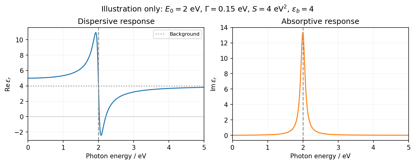
The resonance position is fixed at 2 eV; peak height, width and background are not specified. The figure chooses an explicit finite damping and oscillator strength only to illustrate the shape over 0–5 eV. In particular, a negative real permittivity above resonance is possible for suitable strength and damping, but is not forced by the resonance energy alone. Setting damping exactly to zero would give a singular idealized response instead of a finite-width photon absorption peak.
In the nearly-free electron model, the free parabola is coupled to copies shifted by reciprocal wavevectors . The first degeneracy is at , where the counterpropagating waves have equal kinetic energy. Retaining their coupling gives two branchesConsequently a nonzero Fourier component opens a gap at the zone edge. The dispersion remains approximately free-electron-like away from the crossing, but the branches avoid crossing and their slopes flatten at the band edges. The horizontal axis can be labeled either wavevector , with edges at , or physical momentum , with edges at .
At the edge, an appropriate choice of spatial origin makes real. The eigenstates are equal-weight standing waves. In a normalization length containing an integer number of periods, representative real forms areThey come from the sum and difference of and , up to a global phase. Their densities have maxima and nodes displaced by relative to one another. Both wavefunctions change sign under translation by , as required by their zone-edge Bloch phase, while their densities are lattice-periodic.
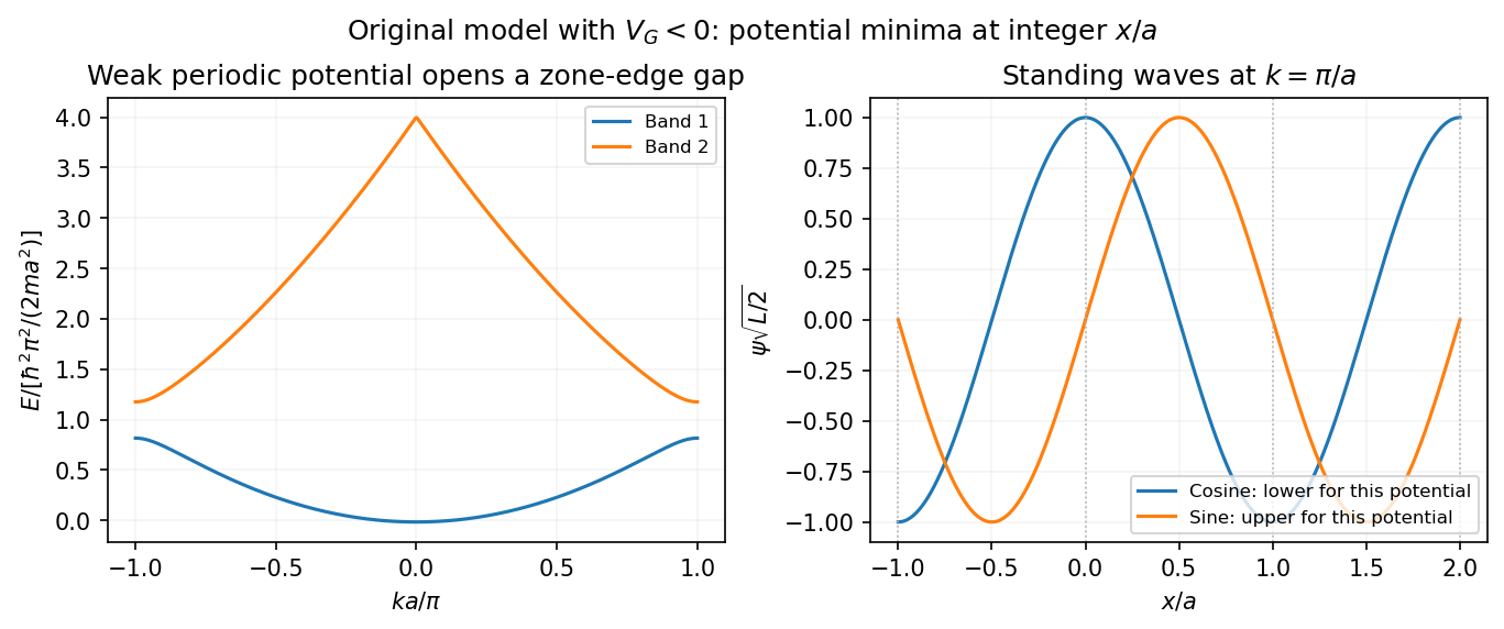


For the figure's choice with , the potential minima occur at . The cosine state puts density there and is lower, while the sine state puts a node there and is higher. Reversing the potential's phase relative to the coordinate origin exchanges that assignment. Since the question supplies only the spatial period, it fixes the zone-edge locations and qualitative standing-wave structure, but not a numerical gap or an origin-independent choice of which drawn sine/cosine is lower.
For one isotropic carrier species in the Drude model, the longitudinal electrical resistivity at zero transverse electric current is , and the Hall electrical resistivity has magnitude . Equivalently, the electric field balances the magnetic deflection through , while . Therefore the magnitude of the Hall angle obeysThe required ratio givesThe electron density cancels. With electric current along and field along , Electrons have negative Hall coefficient and hence ; the requested one-percent condition concerns the magnitude. This calculation assumes Electrons dominate transport and the transverse contacts draw no electric current, so a Hall field can develop.
Articles by others on the same topic
There are currently no matching articles.