Use transverse coordinates (x,x′) and a signed focusing strength K in Hill's equation, x′′+Kx=0. A drift of length ℓ has beam transfer matrixFor a uniform focusing quadrupole magnet with K=κ2>0, and a defocusing one with K=−κ2,The focusing plane has oscillatory trajectories, while the defocusing plane has hyperbolic growth and decay. A magnetic quadrupole focuses one transverse plane and defocuses the other; reversing its gradient interchanges their roles.
D(ℓ)=(10ℓ1).
QF(ℓ)=(cosκℓ−κsinκℓsin(κℓ)/κcosκℓ),QD(ℓ)=(coshκℓκsinhκℓsinh(κℓ)/κcoshκℓ).
If ∣K∣ℓ2≪1 and the element's internal drift can be neglected or assigned separately, its kick may be concentrated at one position. With 1/f=∣K∣ℓ,Both kicks preserve position and change the slope linearly with displacement. All these ideal uncoupled maps have determinant one.
F=(1−1/f01),G=(11/f01).
Maps act on column vectors, so the first element appears at the right of the product. Starting immediately before the focusing kick, one full cell hasMultiplying givesIt has detMx=1, as required for this lossless linear beam optics. The other transverse plane experiences the opposite quadrupole signs, soThe two planes have different envelopes but the same trace and therefore the same stable phase-advance magnitude for this equal-strength doublet.
Mx=D(L2)GD(L1)F.
Mx=(1−L1/f−L1L2/f2−L1/f2L1+L2+L1L2/f1+L1/f).
My=Mxf→−f=(1+L1/f−L1L2/f2−L1/f2L1+L2−L1L2/f1−L1/f).
For a real determinant-one map, bounded generic repeated transport requires eigenvalues e±iμ, equivalently ∣trM∣<2. Here both planes have trM=2−L1L2/f2, soFor positive drift lengths and f>0, this means f>L1L2/2. The equalities are marginal and generally produce a Jordan-block growth rather than stable motion. Moving the reference point changes the map by a similarity transformation, M→PMP−1, so the eigenvalues and full-cell phase advance are unchanged.
0<f2L1L2<4,cosμ=1−2f2L1L2.
Write the stable map using the Courant-Snyder parameters, also called Twiss parameters:At the chosen reference point β=M12/sinμ, α=(M11−M22)/(2sinμ), and γT=−M21/sinμ. Repeated traversal givesIf the full ring contains Nc identical cells, its one-turn phase is Ncμ modulo 2π; n ring turns use nNcμ. The displayed Mn is for n repetitions of the specified cell.
M=(cosμ+αsinμ−γTsinμβsinμcosμ−αsinμ),βγT−α2=1.
Mn=(cosnμ+αsinnμ−γTsinnμβsinnμcosnμ−αsinnμ).
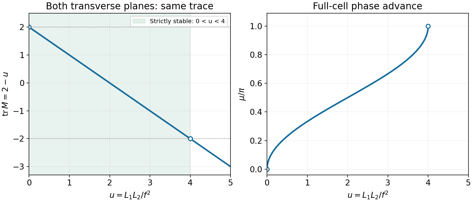
Stability and phase advance of the equal-strength quadrupole cell
. Both transverse planes have trace 2 minus L_1 L_2/f squared. The strict stable interval excludes the two marginal boundaries. Details.
Relativistic radiation is concentrated into an angle of order 1/γ around the instantaneous velocity. The emission direction sweeps past a tangent observer over an orbital interval of order ρ/(γc). Since the charge moves toward the observer, arrival times are compressed by an additional factor of order 1/γ2, giving the spectral scale ω∼cγ3/ρ.
The conventional numerical factor follows from the radiation Fourier phase. Near the tangent direction, circular motion givesWith u=cγt/ρ, this becomes [ωρ/(2cγ3)](u+u3/3). The resulting Airy-type integrals are expressible through modified Bessel functions with tangent-plane argument ξ=ωρ/(3cγ3). The standard angle-integrated synchrotron radiation spectrum has shapeIt therefore identifiesThe beaming argument supplies the physical scaling; the spectral integral fixes the conventional factor 3/2. Critical energy is a broad spectral scale, not a hard photon-energy cutoff.[ref]
ω(t−cn^⋅r(t))≃ω(2γ2t+6ρ2c2t3).
F(x)=x∫x∞K5/3(z)dz,x=ωcω,ξ=2x.
ωc=2ρ3cγ3,ϵc=ℏωc=23ρℏcγ3.
Synchrotron Radiation in the Geant4 Physics Reference Manual by Geant4 Collaboration. Critical energy and critical mode number
For a 5 GeV electron, γe=E/(mec2)≃9785. With ρ=10 m, the stated synchrotron critical frequency formula givesAt the same total beam energy and bend radius, a proton has γp=5/0.9383≃5.329, and the same supplied formula givesThe ratio is (γp/γe)3≃(me/mp)3, explaining the strong suppression for protons. The critical-energy formula is an ultrarelativistic approximation, excellent for the electron and only approximate for this moderately relativistic proton. If “5 GeV proton beam” instead denotes kinetic energy, then γp=1+5/0.9383 and the estimate is about 7.50×10⁻⁶ eV; the two beam-energy conventions should not be mixed.
ϵc,e≃2.77×10⁴eV=27.7keV.
ϵc,p≃4.48×10⁻⁶eV.
Substituting the electron Lorentz factor in the supplied energy-loss formula givesWithout replenishment, the electron's momentum decreases. The reference dipoles then bend it more tightly, producing a displaced orbit. In linear beam optics, x=Dxδ and y=Dyδ, where δ=Δp/p≃−U0/E≃−1.11×10−3 per uncompensated turn. In an ideal planar ring the horizontal dispersion is nonzero and the orbit shifts horizontally, inward where Dx>0. There is no corresponding vertical closed-orbit shift when Dy=0. Real coupling or vertical dispersion can change that idealization.
U0=3ϵ0ρe2γe4≃5.53MeV per turn.
With current I=0.500 A, the number of circulating particles is N=ITrev/e, so the radiated power isThe 2μs revolution time cancels when using beam current. Radio-frequency cavities restore the lost energy longitudinally, with synchronous gain eVRFsinφs=U0 in the sine-phase convention. Their RF power system must supply at least this beam power, in addition to its own losses. Radiation damping and quantum excitation determine beam emittances; they should not be confused with the dispersive closed-orbit shift from a momentum change.
P=TrevNU0=eIU0≃2.76MW.
The quoted proton energies are explicitly kinetic. For mean ring radius Rˉ=215 m,Using these expressions rather than setting β=1 at injection givesThe frequency approaches c/C as energy increases; it is the velocity increase, not a change in the prescribed mean ring circumference, that produces the frequency sweep.
C=2πRˉ,γ=1+0.9383GeVK,β=1−γ−2,frev=Cβc.
frev(4GeV)≃217.880kHz,frev(20GeV)≃221.700kHz,frev(50GeV)≃221.885kHz.
The RF harmonic number is the number of RF cycles per revolution, so fRF=hfrev. For h=32,The synchronous phase fixes which phase of that voltage is sampled, not the frequency ratio. For a sine voltage, φs=0 gives zero net accelerating voltage and describes a stationary ideal-energy condition; an actual energy ramp requires a phase producing the required energy gain. A different phase-origin convention changes that statement about the zero of phase, but not the boxed frequencies.
fRF(4GeV)≃6.97217MHz,fRF(50GeV)≃7.10033MHz.
The instantaneous beam lifetime iswhere losses make dN/dt<0. If the fractional loss rate is constant, N(t)=N0e−t/τ and τ is the time to fall to 1/e of the starting population. At fixed revolution frequency, the circulating current has the same exponential decay. Density-dependent loss mechanisms can make the instantaneous lifetime vary, so a single exponential need not fit every fill.
τ=−dN/dtN,
Particles are lost when a process drives their transverse amplitude or energy outside the machine's accepted region. Principal causes include scattering from residual gas; Touschek scattering within a bunch, which can convert transverse momentum into excessive longitudinal momentum; collision losses at an interaction point; diffusion from nonlinear resonances, field or RF noise; and collective instabilities or insufficient RF acceptance. Mechanical aperture restrictions turn large-amplitude motion into a loss.
Synchrotron-radiation energy loss is normally replenished by RF, so it does not by itself remove one electron for each emitted photon. Rare large energy deviations can nevertheless contribute to losses if they exceed the accepted energy range. Continuous top-up injection can hide the underlying decay and must be accounted for when measuring a lifetime.
Use a calibrated, nonintercepting DC beam current transformer to measure the circulating current repeatedly during a fill, with top-up injection absent or separately recorded. At fixed revolution frequency, I=eNfrev, so a fit to logI versus time gives slope −1/τ for exponential decay. The transformer's zero offset and long-term drift must be controlled, especially at low current. An AC current transformer or a calibrated bunch pickup can additionally resolve bunch charge, whereas a DC transformer provides the total circulating intensity needed here.
Both machines are proposed electron–positron linear colliders, using sources, damping rings, bunch compressors, two opposing main linacs, and final-focus and beam-delivery sections that bring very small bunches to an interaction point. The spent beams go to extraction lines and beam dumps rather than making repeated collision turns.
In the exam-era International Linear Collider reference design, polarized electrons and an undulator-based positron source feed damping rings and two superconducting main linacs; the full 500 GeV centre-of-mass facility is about 31 km long. The Compact Linear Collider adds high-current drive-beam generation and deceleration lines parallel to its main linacs; its 3 TeV concept is roughly 48 km long. The linear layout avoids the repeated synchrotron-radiation losses that would be severe for multi-hundred-GeV electrons in a storage ring. [ref]
https://arxiv.org/abs/0712.2361. ILC Reference Design Report, Volume 3—Accelerator (2007), abstract and overall layout
[ref]https://cds.cern.ch/record/1500095. CLIC Conceptual Design Report, CERN-2012-007, accelerator concept and layout
For a comparison appropriate to this 2012 examination, use the reference-design and conceptual-design targets rather than later revised starting stages:The ILC reference programme included scanning approximately 200–500 GeV and a possible 1 TeV upgrade. The CLIC 2012 studies included lower-energy construction stages as well as the ultimate multi-TeV machine. These are design goals, not achieved operating luminosities.
DesignILC reference designCLIC multi-TeV designs500GeV3TeVL(cm−2s−1)2×10345.9×1034
Collider luminosity sets the event rate for a process of cross-section σ through dN/dt=Lσ; it is not radiated optical power. [ref]
https://arxiv.org/abs/0712.2361. ILC Reference Design Report, Volume 3 (2007), design energy and peak luminosity in the abstract
[ref]https://indico.cern.ch/event/216895/contributions/442123/attachments/347325/484269/lucaci_FCAL.pdf. CLIC CDR status, November 2012, slide 33: staged energies and total luminosities
The International Linear Collider uses externally powered superconducting niobium RF cavities at about 1.3 GHz, with a reference average accelerating gradient of 31.5 MV/m. Superconducting walls reduce RF dissipation, allowing relatively long RF pulses and bunch trains, at the cost of cryogenic infrastructure.
The Compact Linear Collider uses normal-conducting copper structures at about 12 GHz and a main-linac gradient near 100 MV/m in its multi-TeV design. A separate high-current, lower-energy electron drive beam is decelerated in power-extraction structures; the resulting RF power accelerates the high-energy, low-current main beams. This two-beam concept supplies short, high-power pulses without requiring a high-power klystron at every main-beam structure.
ILC: superconducting low-loss RF; CLIC: high-gradient normal-conducting two-beam RF. Both rely on damping and final focusing to obtain very small collision spots, so energy alone does not determine their luminosity. [ref]
https://cds.cern.ch/record/1072192/files/ab-2007-078.pdf. ILC reference gradient and superconducting RF baseline
[ref] Ancestors (9)
- 2012
- Past exam of the short options paper shared by Prelims and Parts A and B of the physics course of the University of Oxford
- Short options paper shared by Prelims and Parts A and B of the physics course of the University of Oxford
- Physics course of the University of Oxford
- Undergraduate course of the University of Oxford
- Course of the University of Oxford
- University of Oxford
- List of universities
- Home
Discussion (0)
New discussionThere are no discussions about this article yet.
Articles by others on the same topic (0)
There are currently no matching articles.